Asides

  • Using Flirc with NVIDIA Shield for use with uControl

    Some devices no longer have built in IR receivers. To enable them to be used with the uControl app you can add a third party device called FLIRC. This connects to a source device via USB and turns IR codes into control commands the source device recognises.

    The Flirc device can be found here – Flirc

    Install the Flirc software on your computer, and install this profile onto your laptop/PC – NVIDIA Shield

    Load up the Flirc software and in the top left click File, and then Load Configuration and choose the NVIDIA Shield profile you have just downloaded

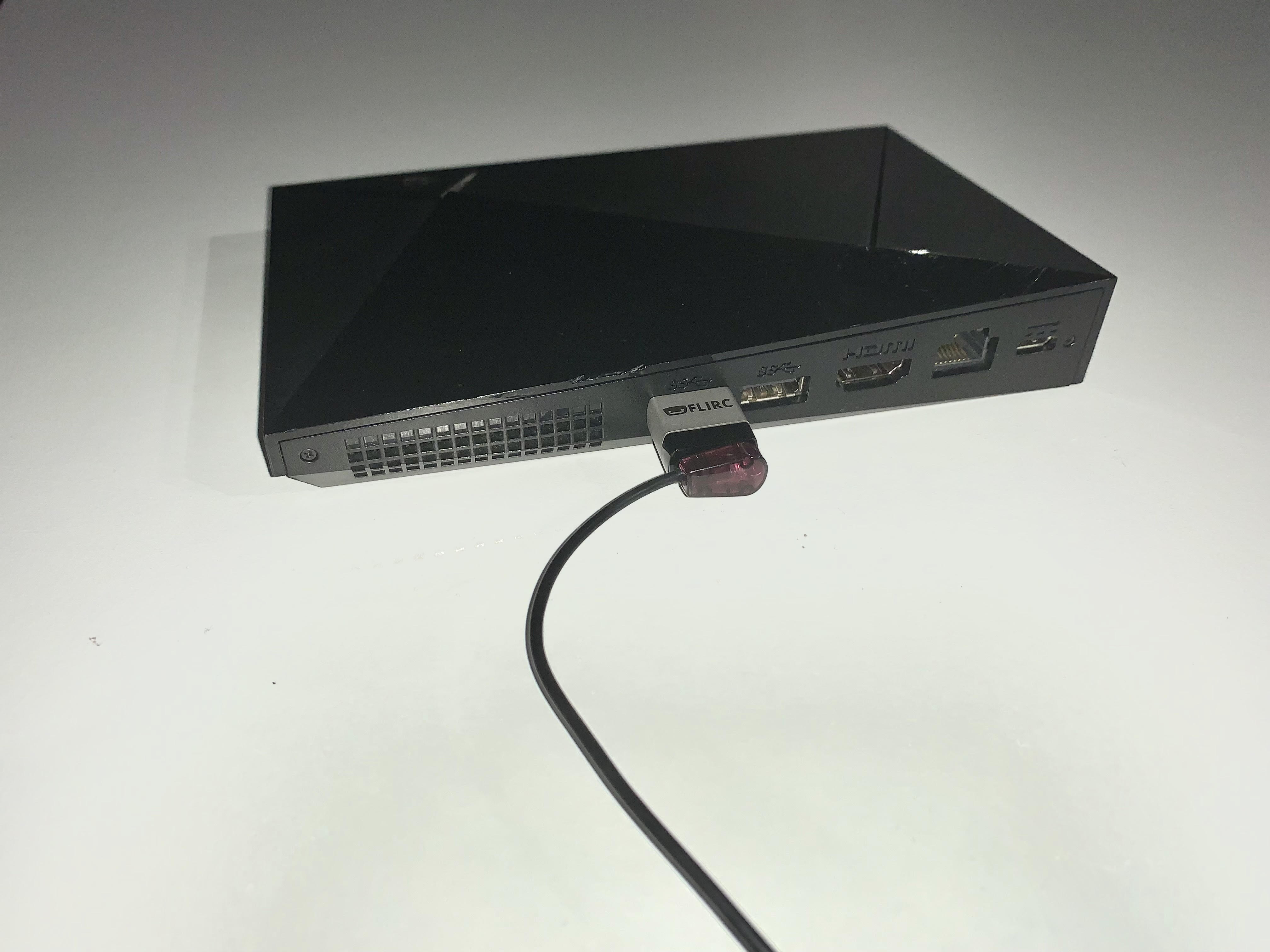
    Remove your Flirc from the laptop/PC and connect it to the female USB port on the back of your NVIDIA Shield. Next place the IR transmitter from you HDANYWHERE device on or near to the Flirc.

      update-mos

    Once this is done you can install the NVIDIA Shield IR pack and control your NVIDIA device with uControl.
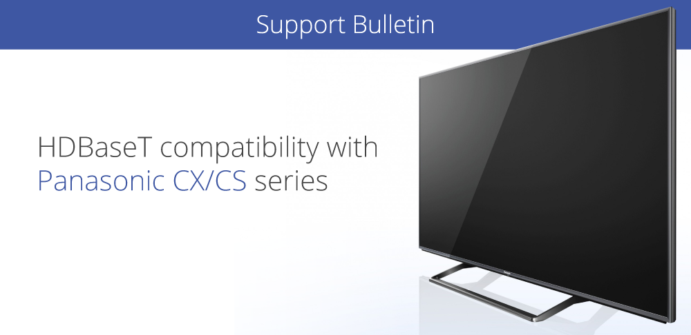
  • HDBaseT compatibility with Panasonic CX/CS series

    blog

    The recent release of Panasonic’s new CX/CS HDTVs feature no support for the HDBaseT transmission technology found in HDanywhere’s multiroom matrices (Modular 4×4 and 8×8 / mHub 4K / 100m Pro Extender).

    This software incompatibility caused these displays to be unable to display picture from HDanywhere products. Please note that this only affects NEW Panasonic CX/CS range displays.

    Yesterday, Panasonic released firmware updates resolving this issue. There is now full compatibility between HDanywhere products and Panasonics entire range of displays.

    A Quick tip for updating the TVs on a network: if you select update firmware in the normal way, it will probably say that it’s already up to date. You need to go to apps then select Netflix, and that will force it to check the update server.

    If your TV isn’t downloading the update automatically you can manually update it.

    For CX you need version 3.206 or higher and for CS you need 3.014 and up.

  • MHUB-OS 8 first boot process

    The first boot process for MHUB-OS has remained largely unchanged with the exception of zones.

    The slideshow below walks you through the steps within MHUB’s first boot process and how to setup zones to refect the different rooms or areas within you property.

    If you wish to configure a stacked system please watch this video – Creating a MHUB stacked system.

    You should be able to complete the process in under 10 minutes.

    MHUB-OS first boot steps are as follows:

    1. EULA and Privacy policy
    2. Name your MHUB
    3. Name your source devices
    4. Create zones
    5. Assign outputs to zones
    6. Confirm zones
    7. Connect MHUB to HDA Cloud
    8. Complete setup

    HDANYWHERE(HDA) recommends that every MHUB install goes through its first boot process to ensure that the MHUB is setup correctly.

    How long does the process take to complete

    If you have an update to install then then first boot usually take about 10 minutes. If there is no update you can normally finish the entire process and have an operational MHUB system well within 5-7 minutes.

    Yes. You do not need to access MHUB-OS if you don’t want to. But this is only recommended if you intend to control you MHUB via a control system. You will also miss the opportunity to increase your warranty period and open your MHUB to additional features or services.

    I don’t want to use MHUB-OS or go through the first boot process, will MHUB work like a normal?

    Yes. You do not need to access MHUB-OS if you don’t want to. But this is only recommended if you intend to control you MHUB via a control system. You will also miss the opportunity to increase your warranty period and open your MHUB to additional features or services.

    I made a mistake in the first boot process, can I go back or make a change?

    Yes. You can go all the way back to the update step and correct any incorrect information you entered. Alternatively, you can also access MHUB-OS (after you have completed first boot) and change anything then.

  • Sending TV audio from MHUB to in-wall or ceiling speakers using MHUB PRO 2.0 and MHUB AUDIO

    Extracting video audio from MHUB and sending it to speakers

    Today’s TVs are very thin with the latest models able to be rolled away into a box! A thinner TV is lighter, easier to install and generally more pleasing to the eye as these new advancements can radically change how your traditional TV looks or is installed into your property.

    These advancements have reduced the space inside the TV to an absolute minimum and often a causality of this is the internal TV speaker. Speakers are either located on the rear of the panel (leading to muffled audio) or underneath and in many cases can not provide the type of audio amplification to match the large screen sizes found in the marketplace today.

    Soundbars have plugged the gap, but they aren’t the solution.

    Soundbars have plugged this gap as customers try to achieve audio reproduction that matches their picture quality. Whilst a soundbar is a simple solution to the problem it fair to say that it doesn’t present itself as the most elegant in that it’s additional (visible) hardware that you need to add to your AV setup. The soundbar is also tied to the function of the TV; so it’s not very easy to listen to music on the same device, for example.

    De-embed the audio and manage it separately.

    Using MHUB it’s possible to extract the audio that would be sent to your TV – or even the audio generated from your TV apps like Disney+ or Netflix and send that to speakers in your room. Additionally, when the TV is off you can listen to music on the same speakers. If your speakers are embedded in your walls or are in the ceiling then you won’t even notice them, but you’ll hear the difference.

    Watch the setup video instead.

    MHUB PRO 2.0 + MHUB AUDIO: how does it work

    To achieve this you will need to use MHUB PRO 2.0 and MHUB AUDIO operating together as one system which we call V&A (video & audio).

    Download the MHUB (V&A) guide.

    The MHUB PRO 2.0 can de-embed the audio from any video stream or TV app (using ARC) and downmix it into 2 channel stereo. This audio is then fed into the inputs on MHUB AUDIO which manages amplification of that audio. If you have inputs that require amplification then you can stack another MHUB AUDIO (up to three times using uControl) or as many as you want if you’re using a control system.

    We are here to help. Let us know if you have any questions…

    .

    Contacting us is super easy and we respond fast. Let us know if you have any questions about setting up a V&A system.

  • Controlling NETIO power switching from uOS

    This guide explains how to control your NETIO PDU from uOS, uControl App and uControl Remote.

    NETIO API

    NETIO power switching in uOS

    What this guide will cover:

    1. Understanding switching outputs, batches, ports and their status.
    2. How to create a NETIO API so that you can control power in the property.
    3. How to add that API into uOS.

    Important: you must have the IP for NETIO first

    You can get the IP address of your NETIO by:

    • Using a network scanner application like Fing on your mobile phone to scan your network.
    • Log into your wireless router and look up NETIO in the DHCP table.

    For the purposes of this guide we are going to pretend that your NETIO PDU is on IP address 192.168.1.15 and your uOS device (MHUB, MZMA or Zone Processor) is on 192.168.1.196. We will use this to illustrate all examples moving forward.

    NETIO ports are simple, port 1 is equal to 1 (p=1) and port 2 is equal to 2 (p=2) and so on. When typing your commands, make sure to follow this logic.

    What a typical NETIO API looks like

    http://192.168.1.15/netio.cgi?pass=1234abcd&output1=1

    In the example above we are going to send a command to the Netio PDU (at 192.168.1.15) to execute a power switch turning output 1 to ON.

    Understanding what those variables in the API above mean:

    pass=1234abcd
    This is the authentication and is user definable and can be changed to the name of the device owner on the NETIO web UI.

    output=
    This is the command variable(s):

    • 0 – Turn OFF
    • 1 – Turn ON
    • 2 – Short OFF delay (restart)
    • 3 – Short ON delay
    • 4 – Toggle (invert the state)
    • 5 – No change
    • 6 – Ignored

    “&”
    This sign allows you to add parameters to your command, every command must be linked by it.

    Testing your APIs

    We recommend that you test every API before you enter them into uOS. All IP based APIs have different requirements when it comes to testing but the NETIO API is great because it is super simple.

    To test your API, open a web browser and enter the full API in the URL window and hit enter.

    Screenshot-2023-05-12-121405

    If you get a response in the web browser similar to the one below, and you heard the NETIO PDU tick to signify a switch, then you’re good to take this command and put it into uOS:

    #

    If it doesn’t work then try the following:

    • Make sure the IP address is correct.
    • Make sure that you do not have any typos.
    • Ensure that your IDs are correct and that you’re observing the correct PDU switch.
    • Make sure that the structure of the API matches our example no spaces, no special characters, data is in the correct case (often lowercase).

    How to add your APIs into uControl

    Need more help with the API? Get in touch.

    All HDA staff are able to help with any API questions you might have including any advanced features. Get in touch for help or assistance.

  • How to build an MHUB S stacked system

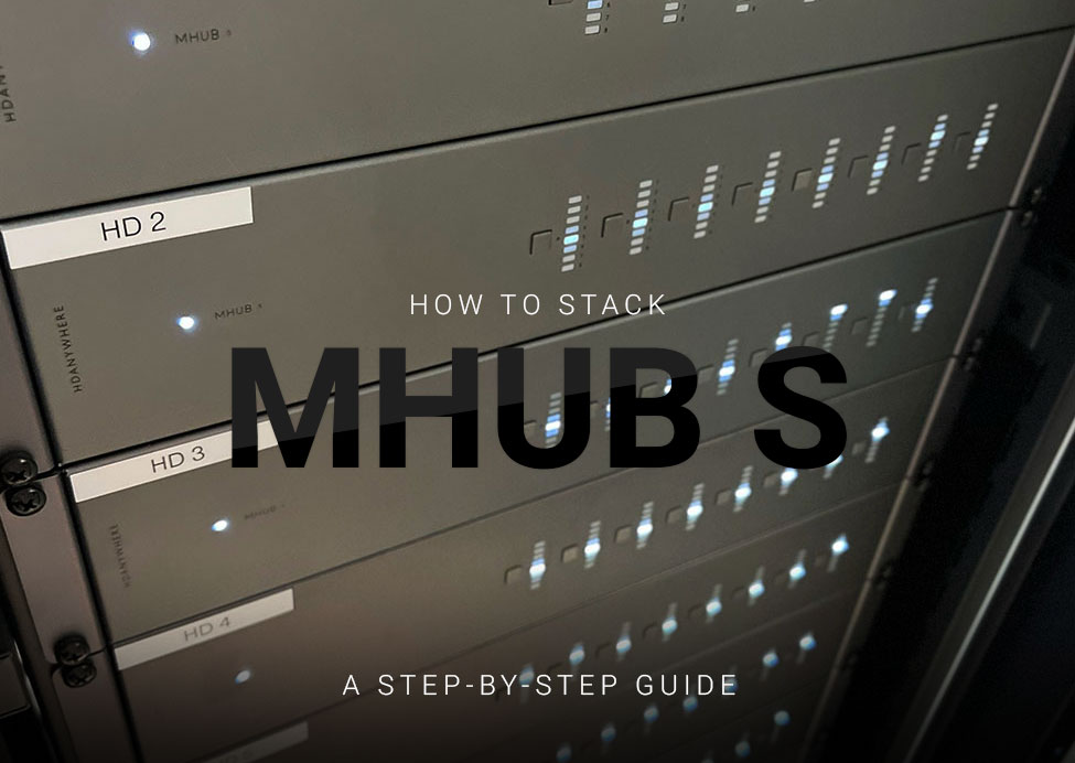
    mhub-s-hero-guide

    Please read:

    This guide will show you how to build a stacked system using two or more MHUB S with uControl acting as the main method of control for the system.

    This guide is intermediate in difficulty and assumes that you have installed MHUB before in standalone mode.

    Make sure the only HDA devices on the network are the ones you want to put into the Stacked System. If you still cannot discover them in the app consider your network infrastructure, the app may struggle to find the system(s) if there are things like network switches in the residence so try simplifying it whilst going through setup.

    It is strongly recommended that you read this guide carefully before commissioning your stacked system to ensure all features of the system work as expected.

    25 minutes (approximately) to work through.

    What you will learn:


    Checklist

    To create a stacked system please make sure you have the following before you start:

    • MHUB S (x2 or more)
    • Zone Processor, uControl Connect (x1)
    • HDMI cable(s) to create connections between your MHUB S systems

    CHECK SOFTWARE VERSIONS:
    Check that ALL hardware above has been updated to the latest software version BEFORE you start configuration on uControl app.


    Glossary

    the following terms are used throughout this guide.

    Foundation Layer

    Foundation Layer

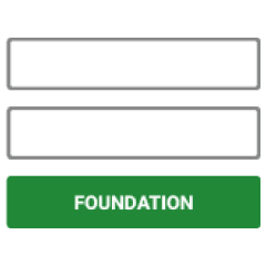
    The MHUB S system which is directly connected to a video source(s) is referred to as the Foundation Layer. Ideally, this system should be physically installed at the bottom of your MHUB S stack. Inside uOS this system is referred to as S1 (see Stack Layer below).

    Connections

    Connections

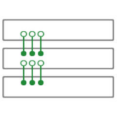
    A Connection is used to define the cabled connections between each component in an MHUB Stack. The combination of HDA devices in your Stack will determine which ports can be paired or not.

    Stack Layer

    Stack Layer

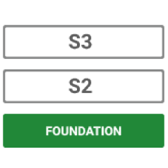
    The Stack Layer is an alphanumeric identifier within uOS, starting from the Foundation Layer (Layer S1). This identifier represents the order of MHUB systems that are connected to one another by a Connection. For example, if you had four MHUB S systems stacked together, then you would start with the Foundation Layer (Layer S1), then the second MHUB S (Layer S2), followed by the third MHUB S (Layer S3) and, finally, the fourth MHUB S (Layer S4).

    IR Cascade

    IR Cascade

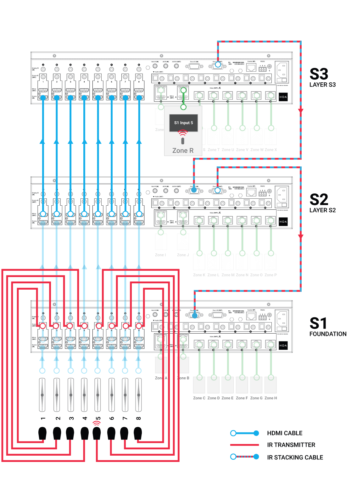
    MHUB S supports infrared (IR) passback from any display receiver connected to any MHUB system to another MHUB, through a process called IR Cascading. IR Cascading works from the top of your Stack, down the MHUB Stack Layers, until it reaches the Foundation Layer Source IR outputs or is instructed to stop elsewhere by uOS.

    Master / Controller

    Master / Controller

    An HDA device (like a Zone Processor) designed to control MHUB and/or MZMA systems operating in Stack mode. Any Stack that needs to be controlled by uControl must have a Master / Controller present in your setup. This is identified as M1 in uOS.

    uControl

    uControl

    uControl is our control system for configuration and control of stacked systems. When we refer to “uControl” in this article we are referring to our app specifically.


    Wiring

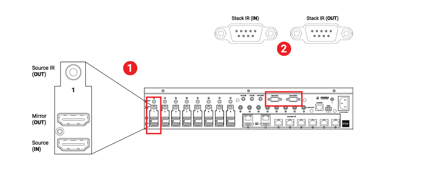
    Stacking video and cascading IR is made possible by two ports on the rear of each MHUB S.

    1. “Mirror (OUT)” port
      Connect the mirror out HDMI port to each Source Input at the Foundation Layer MHUB to the corresponding Source In HDMI port of the next MHUB in the stack.
    2. “Stack IR (IN)” & “Stack IR (OUT)” ports
      (Only needed if you are using IR Passback in your stack)
      Used for MHUB S’ IR Cascading function and can be connected using the Source IR Stacking Cable included with MHUB S. Stack IR only works with a maximum of 4 MHUB S systems.
    Ports used in stacking
    Figure 1: Ports used for stacking video and transporting IR commands (cascade). You will need to identify these ports to stack into other MHUB systems
    1. Using HDMI cables, connect your video input/source to the lowest MHUB in your stack (Foundation Layer) first. Connect them to the “Source (IN)” port.
    2. Repeat step 1 for every video/input source.
    3. From the Foundation Layer locate the “Mirror (OUT)” port and connect a short HDMI cable to it. Complete this connection by connecting the HDMI cable to the “Source (IN)” port on the MHUB S in the layer above.
    4. Repeat step 3 for every MHUB S in your stack.
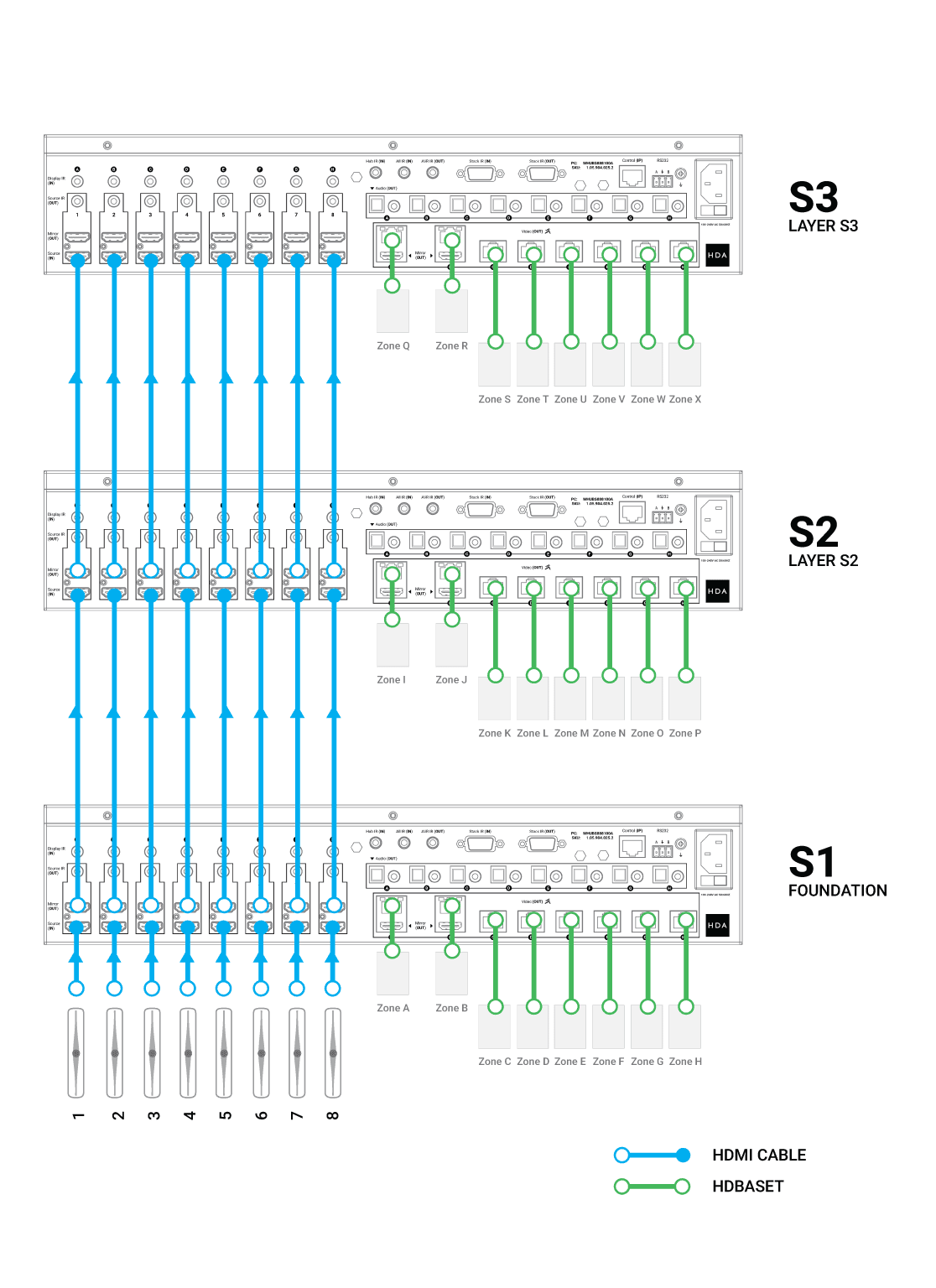
    Wiring example for 8x24 system MHUB S
    Figure 2: (8×24) system wiring example: Connect from the Foundation Layer UP the MHUB S stack as many times as neeeded.

    Watch video: How to wire MHUB S to create a stack

    This video describes how to wire MHUB S systems together to create a stack.

    Watch video: IR Cascading

    If you plan to control your video input/sources using the original source remote control from displays served by stacked MHUB S then you will need to cascade IR down your stack.

    There are some general rules to follow when doing this:

    • Cascading IR applies to source control only. You cannot Cascade IR to displays.
    • Cascading IR goes down the Stacking Layers only, from last to first.
    • Similar to Connections, IR Cascading can only be defined between incremental Stacking Layers: S3 to S2 and finally S1. It is not possible to jump between devices, for example, S3 to S1.
    • The Source IR Stacking Cable is 50cm/1.64ft so bear this in mind when rack mounting MHUB S, you must use the one supplied with the full kit.
    • All “Source IR (OUT)” ports have two modes: Local and Passthrough. If the port is set to Local, then any IR received from a stacked MHUB will be transmitted on the receiving MHUB. If the port mode is Passthrough then the IR signal will be transported off that MHUB down the Stack Layer until it reaches an instruction to execute the IR command Locally.
    • IMPORTANT: Local and Passthrough modes can be set from uOS on the Zone Processor.
    • Any input served from a “Mirror (Out)” port must match the “Source (IN)” port identifier. You can not switch port IDs (eg. Mirror 1 to Input 4)
    Wiring example for 8x24 system MHUB S
    Figure 3: In this 8×24 system a native video source remote control (in Zone R) is being used to send IR commands through the MHUB S stack from S3 back to S1 Foundation Layer and correctly sent to the source being watched in Zone R.

    How to wire MHUB S for IR cascading

    This video describes how to send IR from a stacked MHUB S to the Foundation Layer.


    Initialising your Stacked System using uControl

    Ensure that your MHUB S systems are correctly wired for stacking covered in the part above and that the following is completed:

    • All MHUB S systems in your stack are powered ON.
    • Your Master / Controller device (Zone Processor or uControl Connect) is powered ON.
    • All MHUB S systems and the Master Controller are all connected to the LAN and reachable by their IP address.
    • IMPORTANT: All hardware has been individually updated to the latest software version.

    Configuring MHUB to operate in stacked mode can not be undone without resetting the system and starting again. Ensure that you have your wiring information handy and that you know exactly how the system is connected together before initialising your stack.

    1. Connect to system

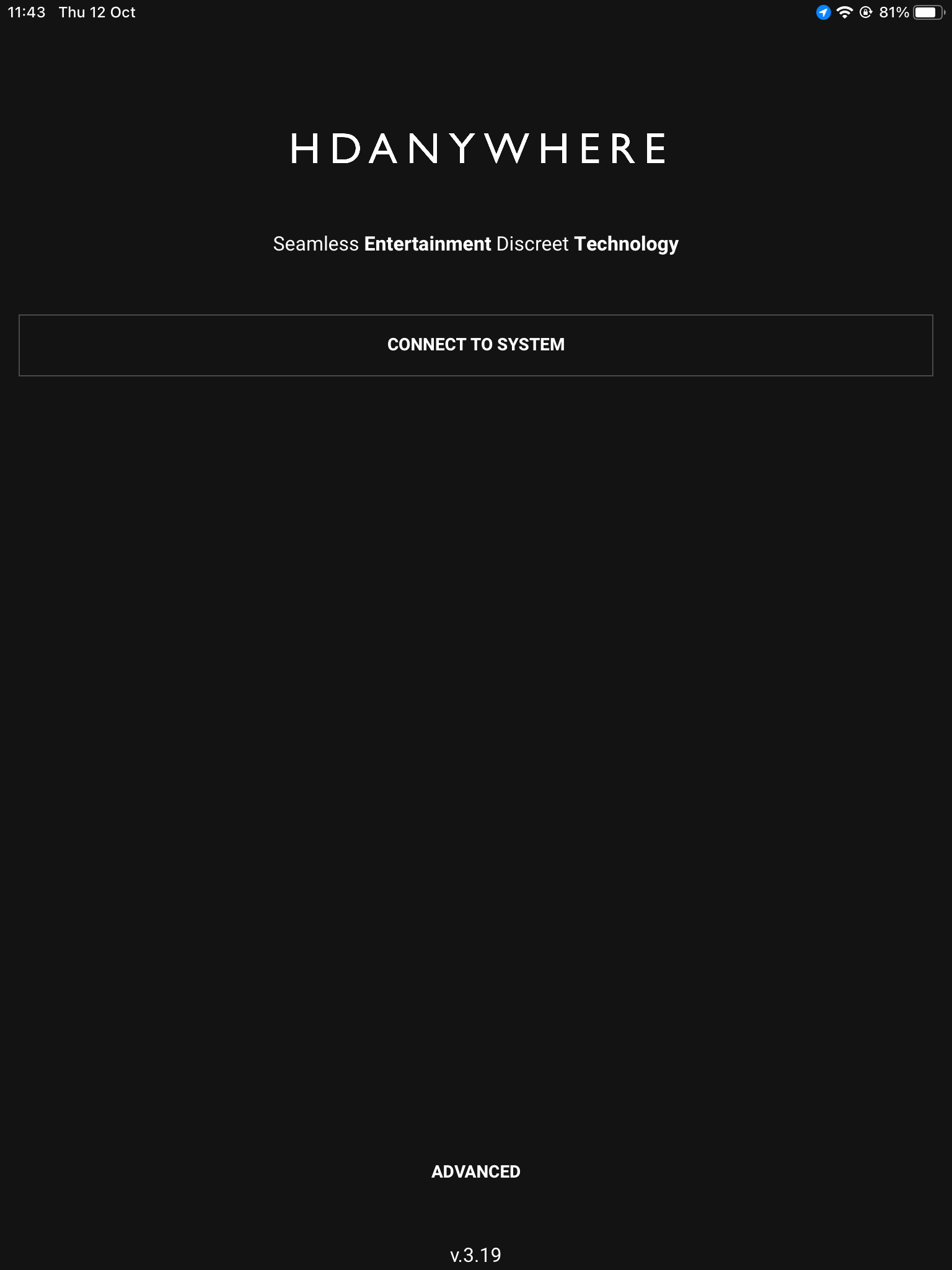
    To get started press connect to system on the uControl Homepage.

    2. Stack

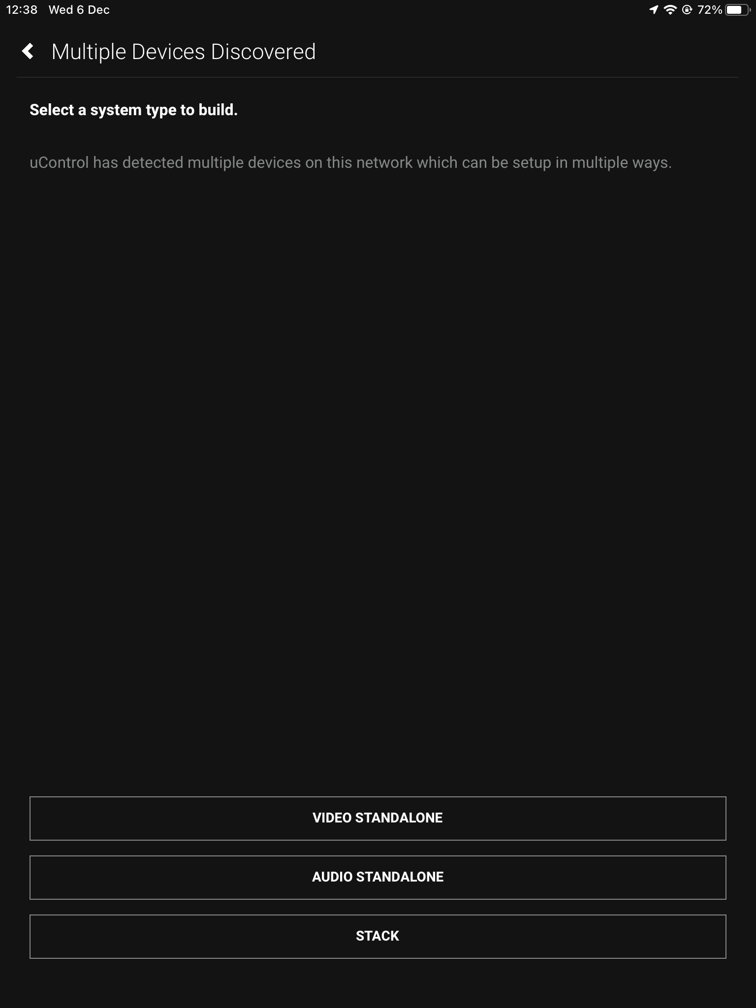
    If the HDA devices are on the network you will be presented with the option to create a stack, video standalone or audio standalone, as this contains two MHUB S’ it is a Stack.

    3. Master Controller

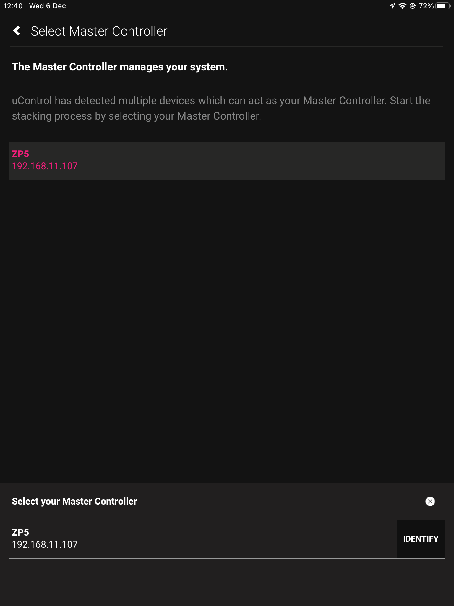
    The Zone Processor acts as the bridge between 2 or more HDA devices and all data goes through this device, acting as a brain. It needs to be selected as the Master Controller.

    4. Setting Stack Layers

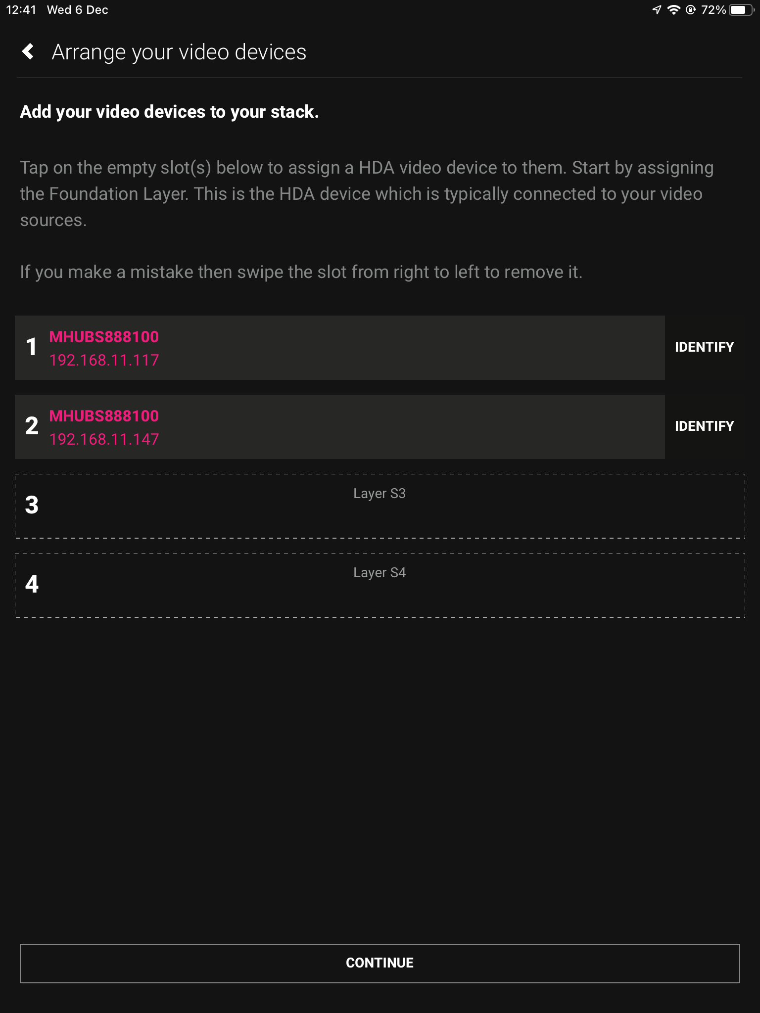
    Next we need to choose our layers, starting with the Foundation Layer. Press identify to the right of the HDA device to make the power LED blink, when you know which is which select your primary MHUB for 1 and the other HDA device for 2, then hit continue.

    4b. Order of layers

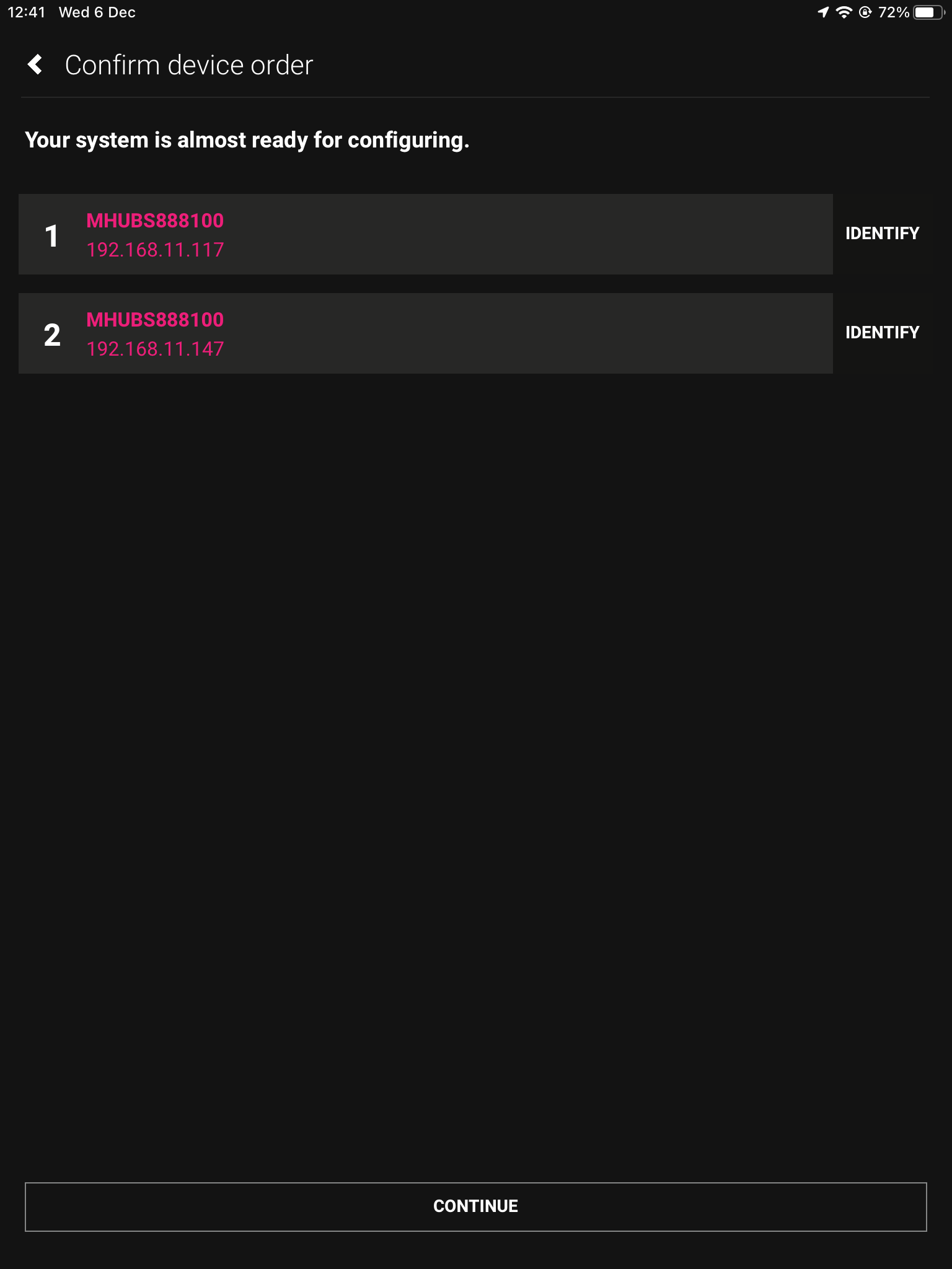
    The order of your physical stack may be different to the order in uControl, as the MHUB with the IP address 192.168.11.147 could be the Foundation layer. It is important to mirror the order of the MHUB’s.

    5. Naming devices

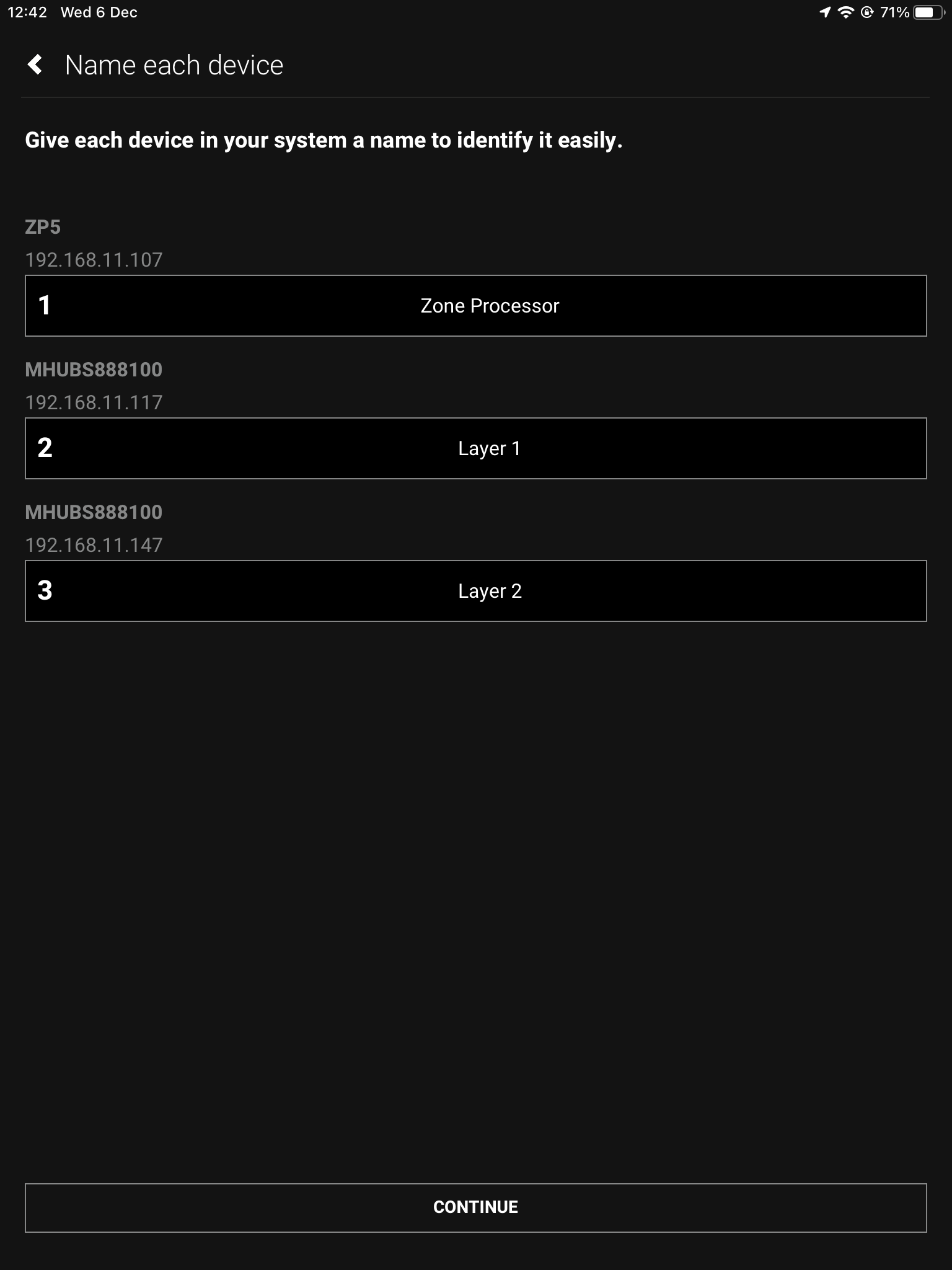
    Name the devices so that they’re easily identifiable.

    6. Access uControl

    Your MHUB’s are now in Stack mode and are ready for configuration. You can now proceed to perform First Boot of your Stack with the Master Controller (M1)

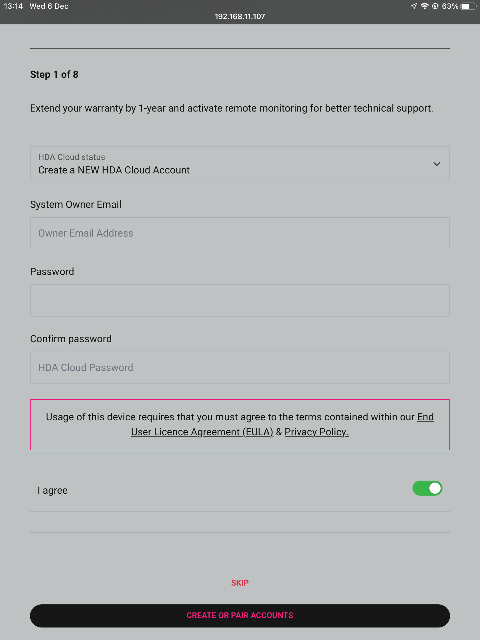
    7. Owner Account

    Owner Accounts allow installers to add their HDA PRO account to their system for additional features, and to increase the warranty period. We recommend you do not skip this step.

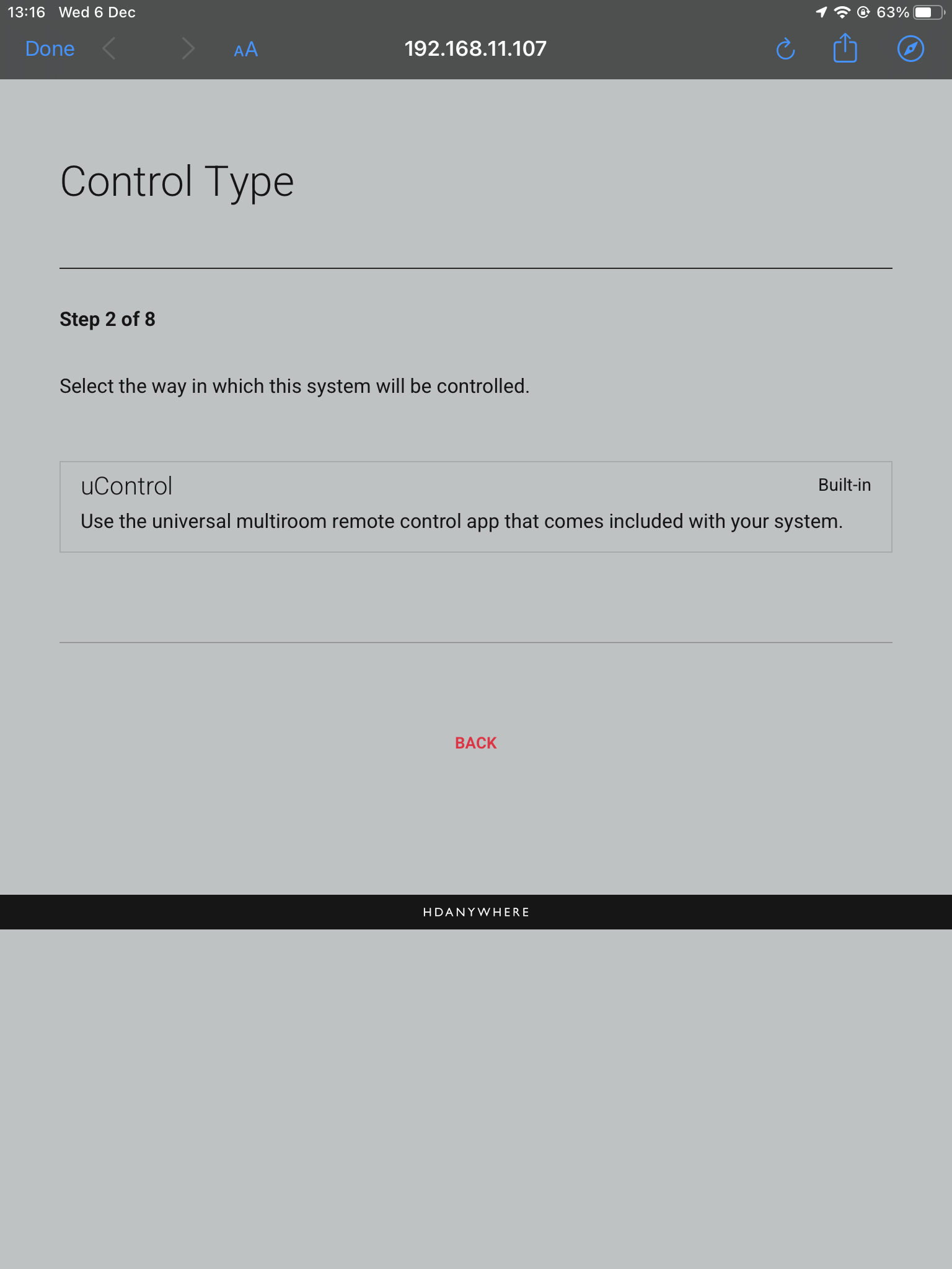
    8. Control Type

    Choose uControl as the Control Type.

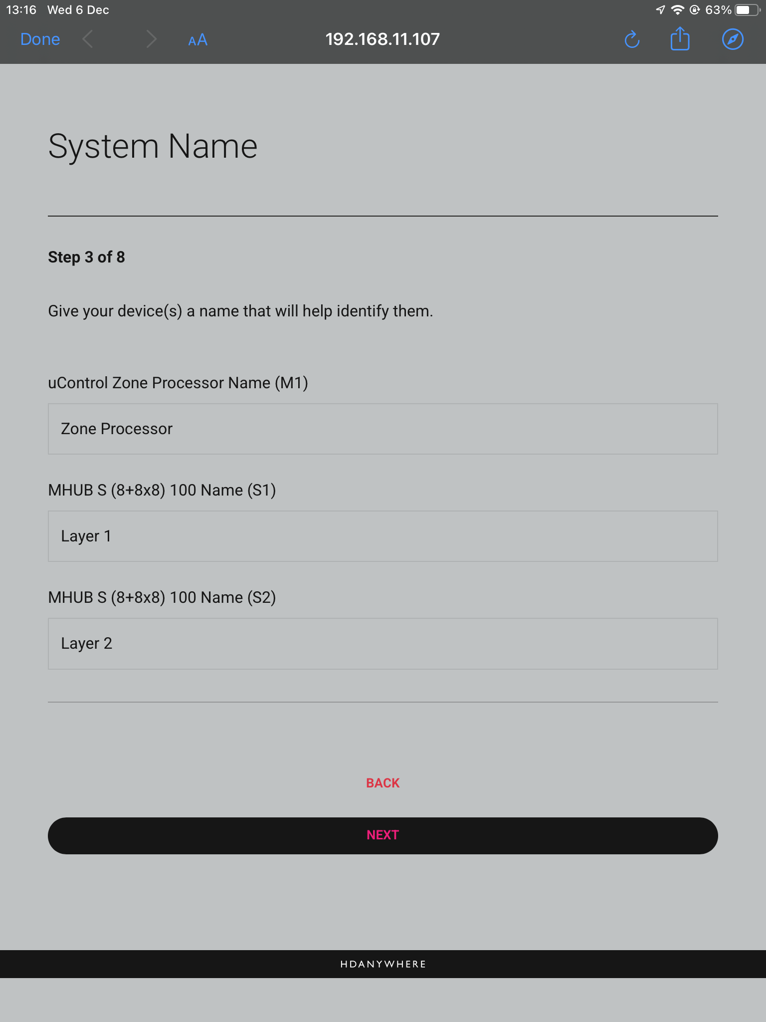
    9. System Name

    Confirm the names of your devices.

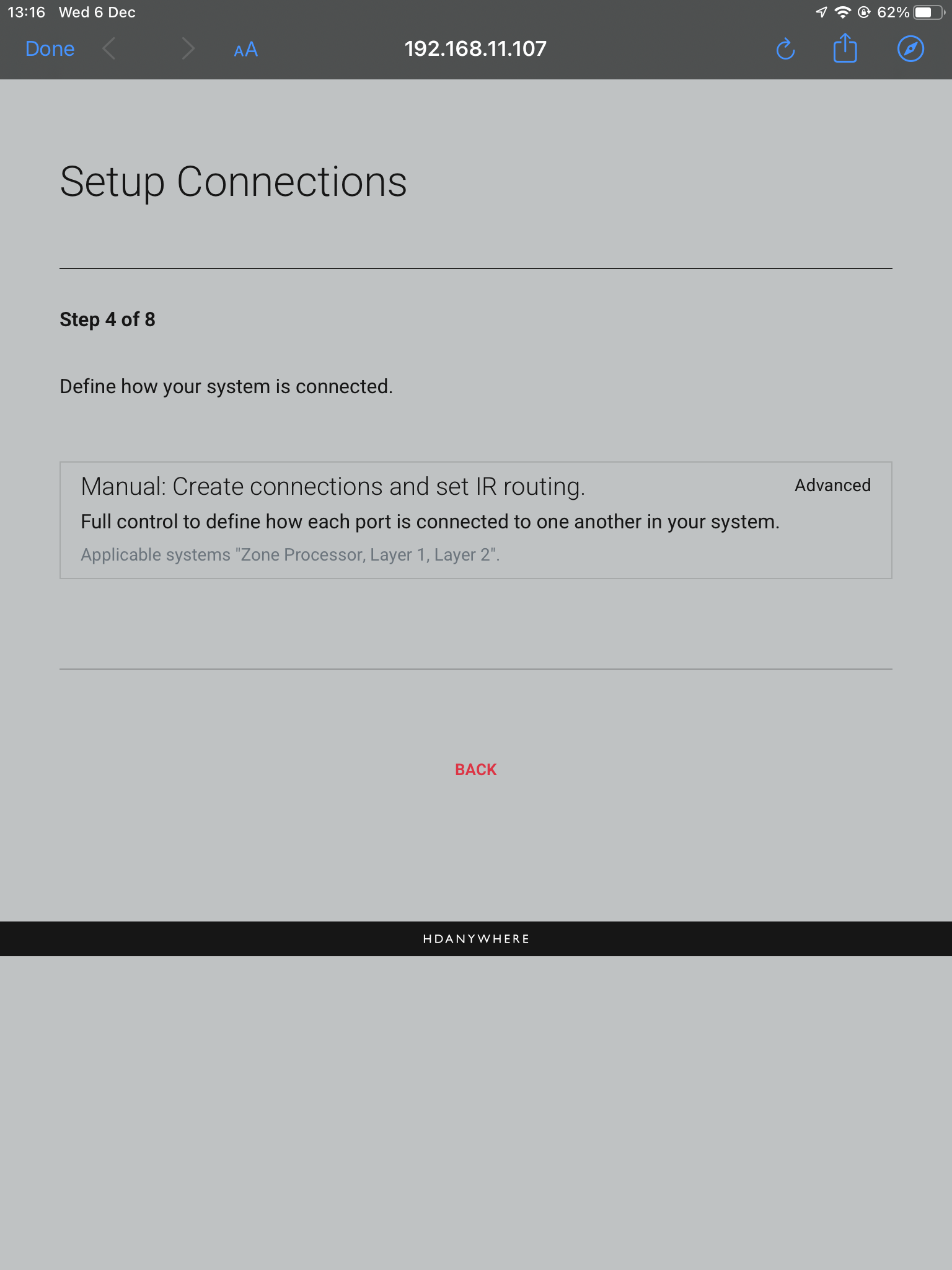
    10. Setup Connections

    This next step will allow us to make the manual connections between the multiple devices.

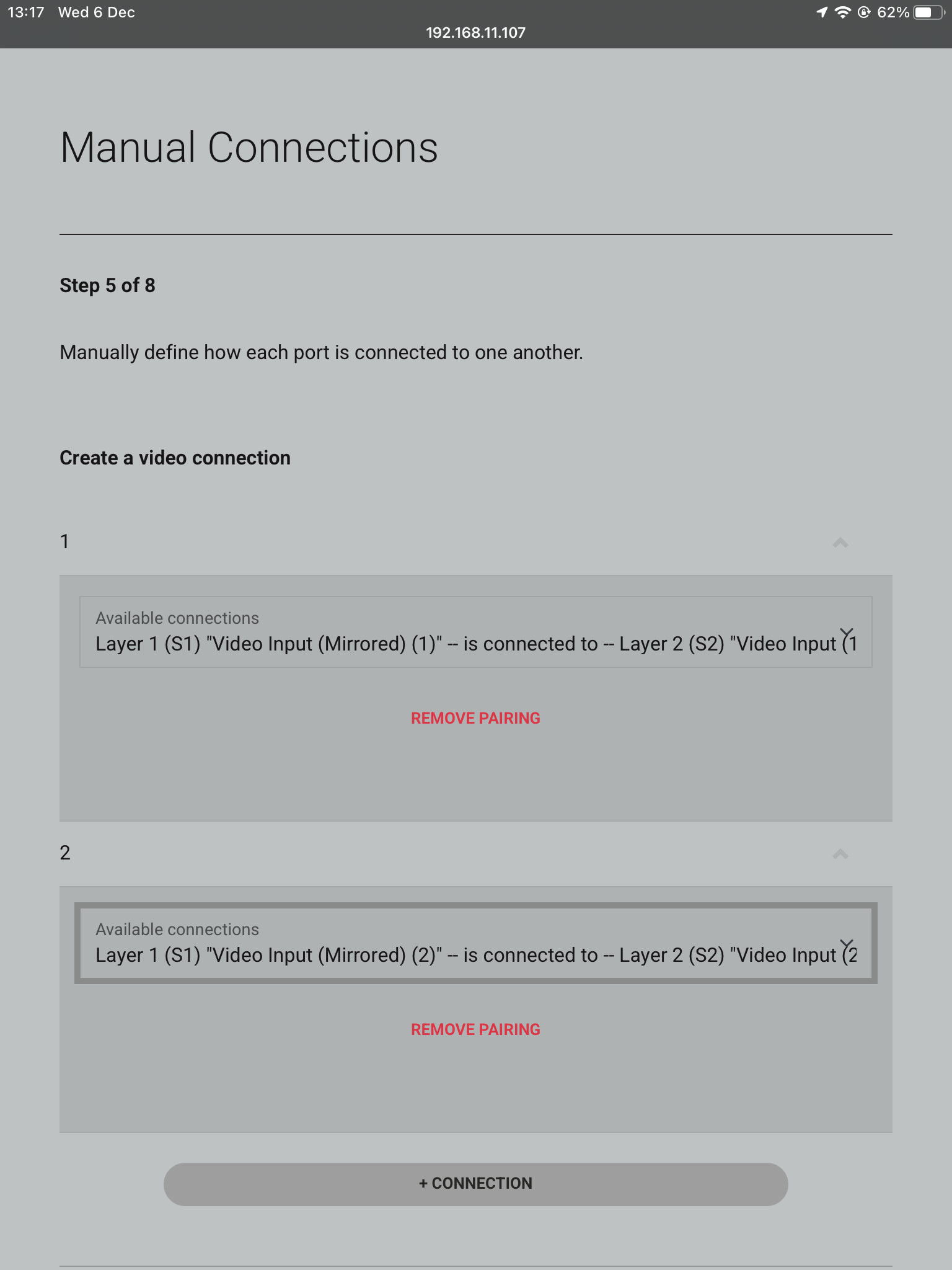
    11. Manual Connections

    This is where you tell the system how it is all linked. In this example source device 1 will be connected to Source (In)1 of the first layer (S1) in the stack and then mirrored with a shorter HDMI cable going into Source (In)1 of the second layer (S2), meaning the source will be available on both MHUB’s and therefore more zones. The same goes for Input 2 being paired with Source 2 on the second layer. Make sure to repeat how ever many times needed for your amount of source devices.

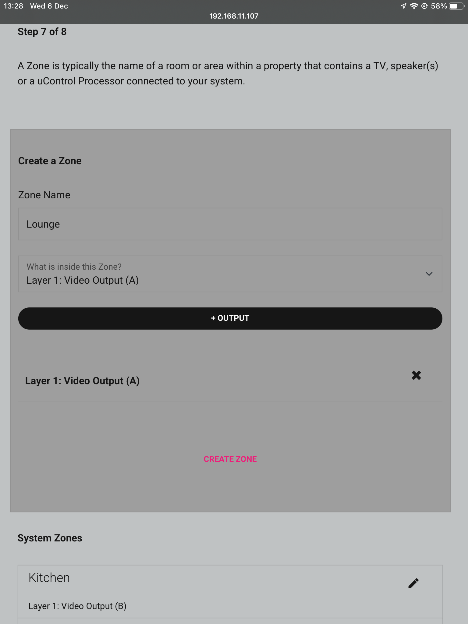
    12. Zones

    A zone is where a display is located, so name the zones after the room those displays are in. To add an output to a zone, choose which output from the list and then press “+OUTPUT”, check that the output has been added below in bold and then press “Create Zone”. Repeat process for all zones.

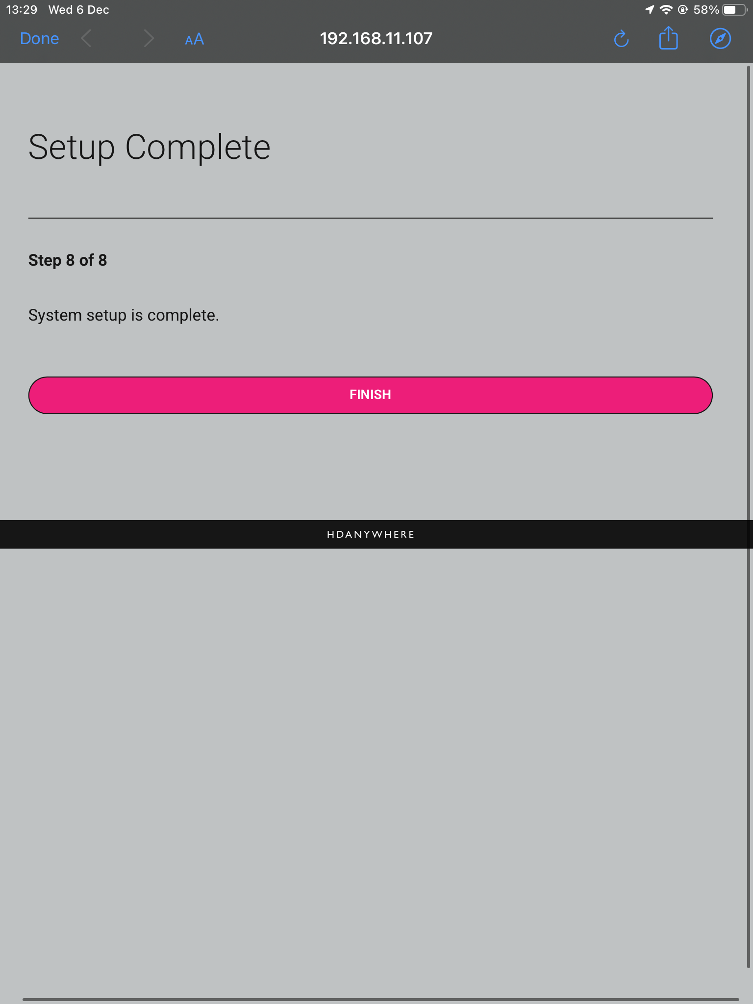
    13. Complete

    Now the system has been configured press “Finish” and you will be taken out of the web interface.

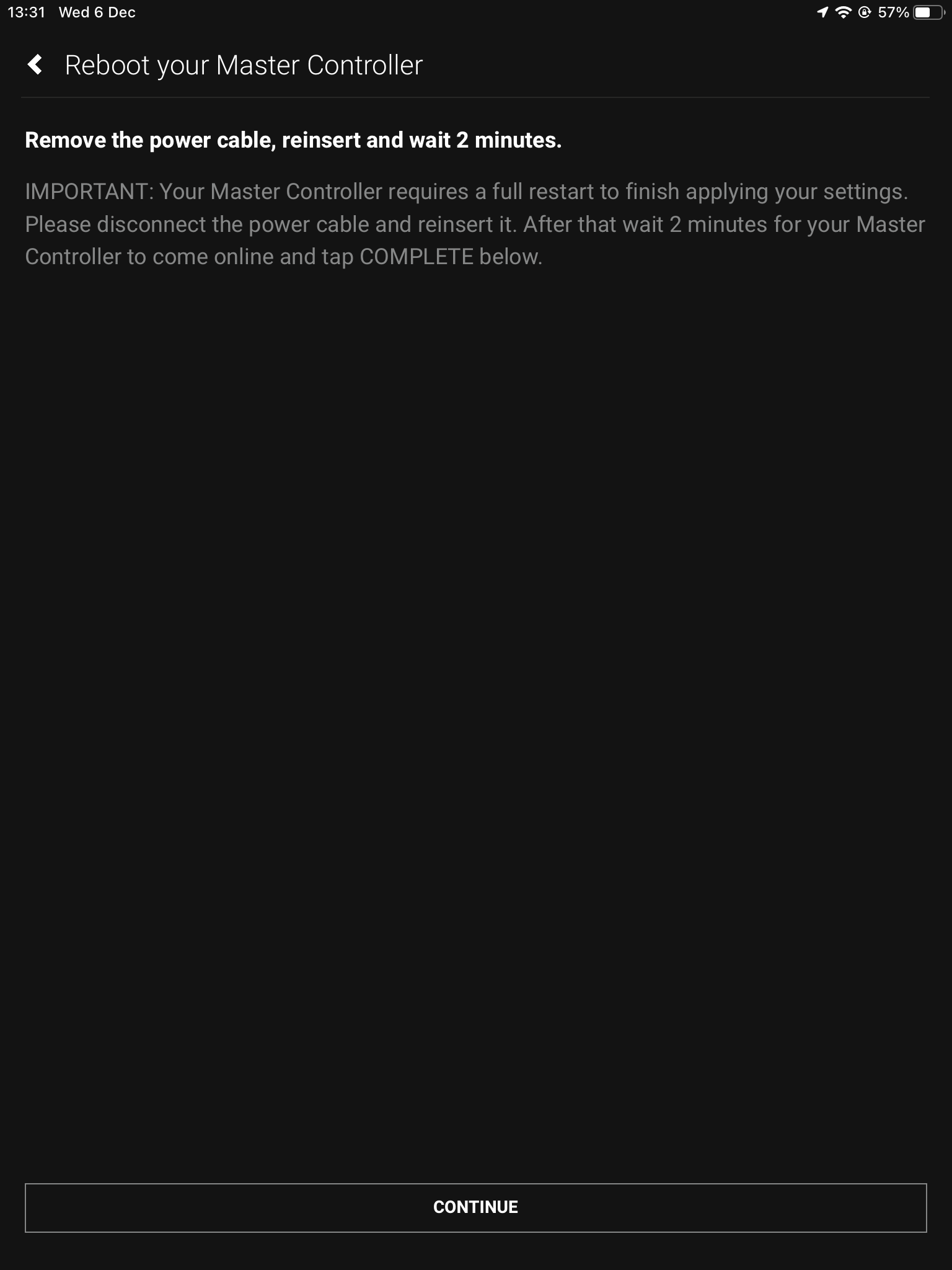
    14. Reboot

    The last step is to remove the power cable from your Zone Processor and wait 2 minutes, then plug it back in. This is needed to apply the settings you have just changed, once the 2 minutes is up press “Continue”.


    After hitting continue you will be taken into the uControl interface where you can begin setting up the necessary packs and additional features like Functions and Sequences. For more guides on setting up systems after the first boot, please refer to our uOS support page.


  • mHub 2K control system integration

    The mHub 2K range has full support for most popular control systems via serial (RS232) or IP.

    All control strings and current available drivers are available in the mHub control pack, available here – mHub Control Pack

    To control the mHub 2k unit via IP you will first need to discover it by using the mHub controller software available in the control pack.

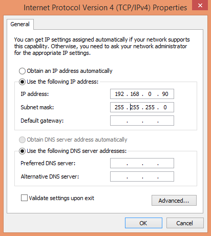
    The mhub 2K’s IP address is pre-configured as 192.168.0.100, your computer will need to have it’s IPV4 range configured to be within the same range initially while you setup the matrix. To configure your IPV4 settings you will need to navigate to the following menu

    ->Network and sharing center
    —>Ethernet
    —–>Properties
    ——->Internet Protocol Version 4 (TCP/IPv4)
    ———>Properties

    IPV4

    Configure your settings as shown in the image, this will change your computer IP range and you will temporarily lose internet connectivity (if your previous IP range was different from this)

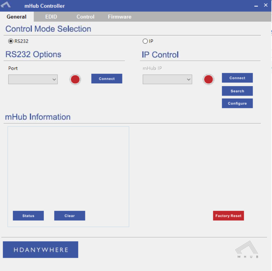
    Once you have changed the IP settings on your PC, open the Mhub controller software

    mhub controller pic 1

    In the mHub controller software select IP and then press the ‘search’ button, this should locate your mHub matrix. Press ‘connect’ the red button should turn green.

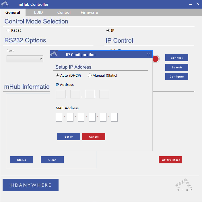
    Press the configure button

    mHub IP

    Change the IP configuration to manual (static), and then enter an IP address within your home network range that is not currently being used and then click ‘Set IP’.

    You can now go back into your IPV4 settings and set them back as they were before (obtain an IP address automatically)

    Your matrix is now on your home network and will be able to receive IP commands from whatever control system you are using.

    Looking for the mHub 4K information, go here – mHub 4K

  • MHUB-OS 8: a quick guide to zones

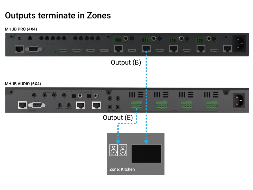
    Zones define a physical space in a property where outputs from MHUB terminate.

    A Zone can include a maximum of 1 video output and a maximum of 4 audio outputs. For example, you can create a zone called “Kitchen” and assign 1 video and 1 audio output to it to provide you with viewable TV and sound. A Zone must contain at least 1 output from an MHUB for it to be addressable for control. Note: outputs can not be shared or split to more than 1 Zone.

    MHUB zones

  • How to deal with Picture loss/dropout on your display(s) when using MHUB

    ​Your MHUB is similar to a central heating system in that there are many components that all need to come together to deliver a working system. An intermittent or full loss in picture on one or more displays can be down to a number of things.

    • HDMI cables going into MHUB and from the display receivers to the displays
    • Your network cabling infrastructure, the termination quality, the distance of the cable run and the number of times that cable runs through patch panels or wall plates.
    • The physical output port on the MHUB
    • The display receivers
    • The actual source devices (more common than you think!) and the AV they are outputting (4K, 1080p, surround sound, HDCP format etc)

    Unfortunately, there is no fast way to determine this. To do this test correctly you will need to test for several days to ensure the results are accurate and your system is stable.

    If dropout occurs on one display in your property…

    The first thing to do is disconnect all sources and outputs from MHUB so you are left with 1 source (preferably the source you notice picture loss on) and 1 output (preferably the display you notice picture loss most frequently on).

    Grab a piece of paper and log the following outcomes when you test the following:

    1. If picture loss is happening only in one location in your property then take a display receiver (and the HDMI cable going into the display) from a known working location and swap it in the area you’re noticing picture loss.
    2. If you still experience picture loss then run freshly terminated Cat 6 cable from the MHUB to the display receiver point-to-point (no breaks in cable) and check again.
    3. If you are still having a problem then connect your new Cat 6 cable to another output port on MHUB.
    4. If #3 doesn’t resolve the problem then disconnect your source from MHUB (and the HDMI cable) and plug it directly into your test display using the same HDMI cable.
    5. If the picture is stable then take the source and the HDMI cable back to MHUB and plug it into another HDMI input and test for picture loss on your display.
    6. Finally, drop the resolution on your HDMI source to something you know the display will accept easily (something like 1080p Stereo)

    If dropout occurs on all displays in your property…

    Start by disconnecting your source from MHUB (and the HDMI cable) and plug it directly into a test display using the same HDMI cable.

    Grab a piece of paper and log the following outcomes when you test the following:

    1. If the picture is stable then take the source and the HDMI cable back to MHUB and plug it into another HDMI input and test for picture loss on your display.
    2. If you still experience loss in picture then drop the resolution on your HDMI source to something you know the displays will accept easily (something like 1080p Stereo)
    3. Remove all outputs from MHUB until you’re left with only one output connected, it could be any port but we recommend starting with A. Check for a stable picture and repeat for each output port individually.
    4. If all ports passed the test in #4 then start connecting additional outputs back to MHUB starting B (so you should have A + B now), if the picture is stable add output C and so on.

    If you log any problems or positives with each test then let us know and we can assist you further.

  • Controlling Gen 1 Shelly devices from uOS

    This guide explains how to pull data from Shelly’s API so you can control it directly from uOS.

    Shelly in uOS

    Please note: this guide covers how to execute a command for a Shelly light, if you are using a different device the same logic applies, you only need to change the parameters. Please find the link to Shelly’s API document below for commands relating to different devices.

    What this guide will cover:

    1. How to control Shelly lighting in your home.
    2. How to add that API into uOS.

    Important: you must have the IP addresses first

    There are a few ways you can get the IP address if your Shelly device:

    1. Use a network scanner app like Fing to find Shelly on your network.
    2. Log into your wireless router and look for Shelly in the DHCP table.

    What a typical Shelly command looks like

    /color/0?turn=on&red=0&blue=0&green=255

    This only shows the logic of a Shelly command, you may be controlling a relay and therefore need to use different parameters. There will be a link at the bottom which will take you to Shelly’s API documentation where you can find all their codes.

    /color/0?
    This is the mode of the device and declares it is an RGBW2 controller. If you were writing a command for an automated blind it would be /relay/0?.

    turn=on
    This affects the state of the device.

    red=0&blue=0&green=255

    Testing your APIs

    You can test your Shelly command in the URL to see if it works. Make sure to include http:// for it to work properly.

    If it doesn’t work then try the following:

    • Make sure the IP address is correct.
    • Make sure that you do not have any typos.
    • Ensure that your IDs are correct and that you’re observing a light in the correct room and location.
    • Make sure that the structure of the API matches our example no spaces, no special characters, data is in the correct case (often lowercase).

    How to add your APIs into uControl

    Need more help with the API? Get in touch.

    All HDA staff are able to help with any API questions you might have including any advanced features. Get in touch for help or assistance.