Asides

  • Installing uControl Packs

    If your HDA device has uControl, you can download IR or IP packs to control thousands of third party devices from the interface of the uControl mobile app. In this guide you will see how to browse our extensive library to download and control the packs for your devices.


    In this support article:


    Installing uControl Packs from uControl

    1. Open uControl

    From the main screen navigate to the menu in the top left.
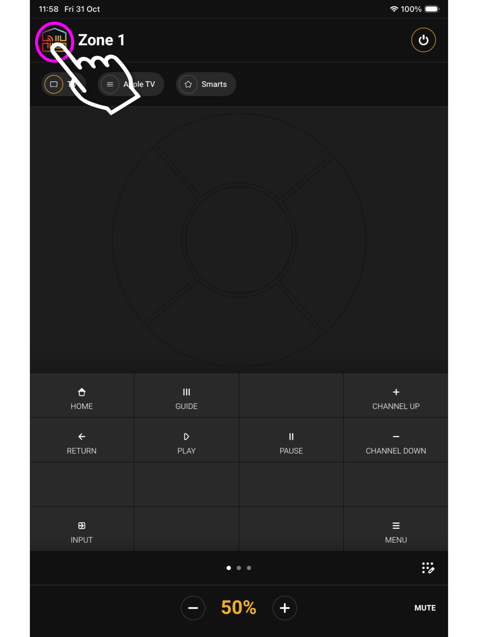
    image 1
    What you see on the main screen may differ, however, the house icon will still be there.

    2. Navigate to your settings

    Look for ‘System Settings’ located in the bottom left corner.
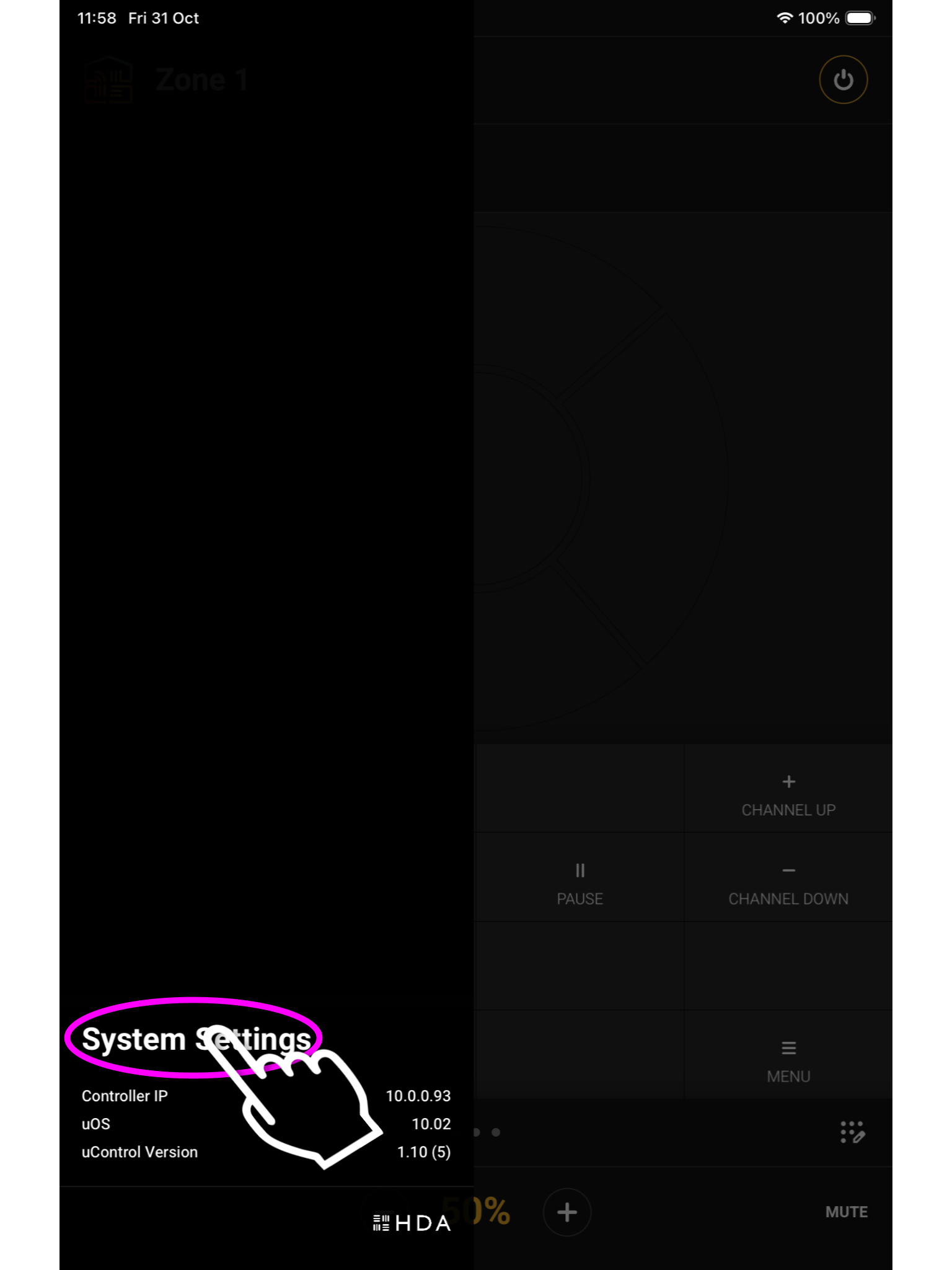
    image 2
    It will be in the bottom left corner.

    3. Access System

    From here press Access System.
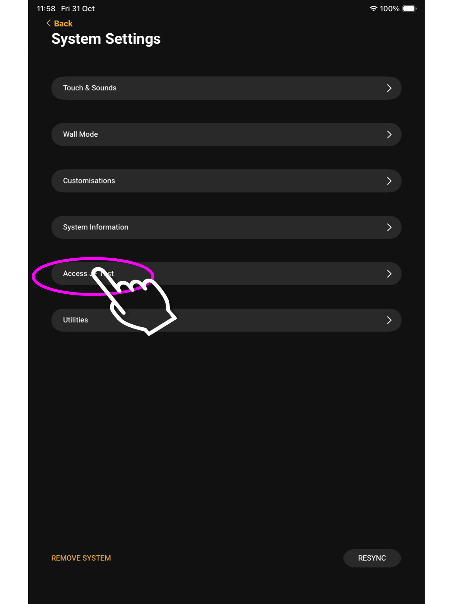
    image 3
    Click Access [system name], the name you configured in uOS will be shown here

    4. uControl Packs

    In this menu press “Manage uControl Packs”.
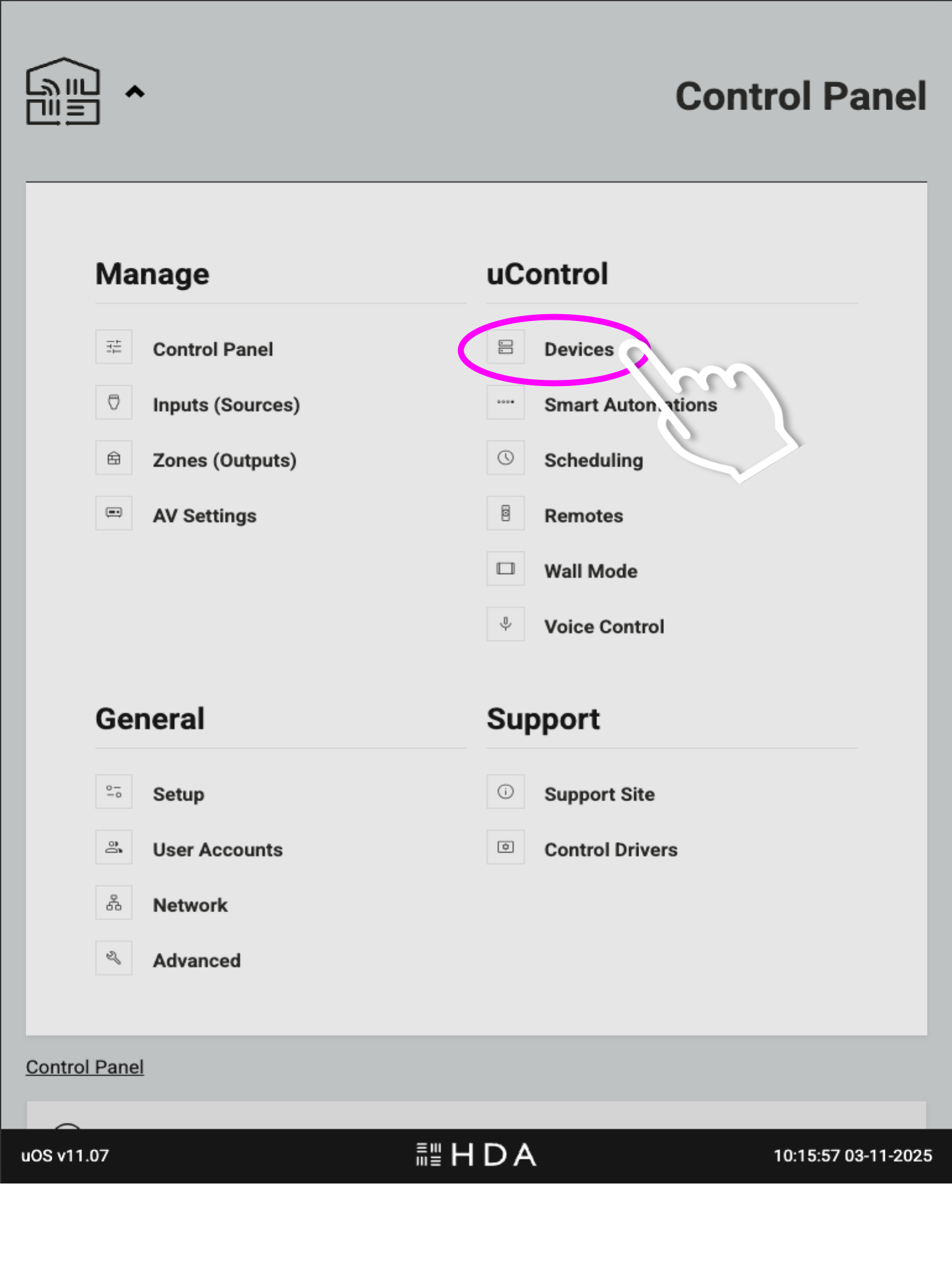
    Open the menu and select ‘Devices’. This will take you to the page where you can download IR and IP packs, and also create IP connections for integrating 3rd party controllers.

    5. Add New

    Now we are in uOS press Add New and a pop up window will appear, press AV Device.
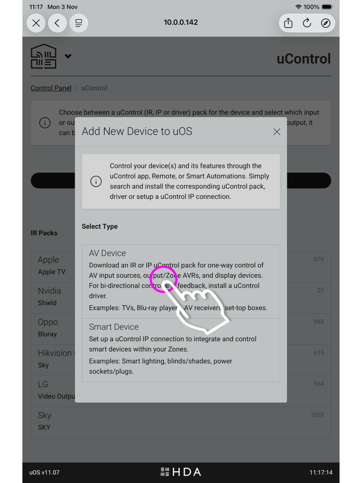
    The below option (Smart Device), is for integrating third party controllers to be controlled by uOS.

    6. Port Select

    You must now select if you’re installing a pack for a source device,a display/output or assigning it to a zone.
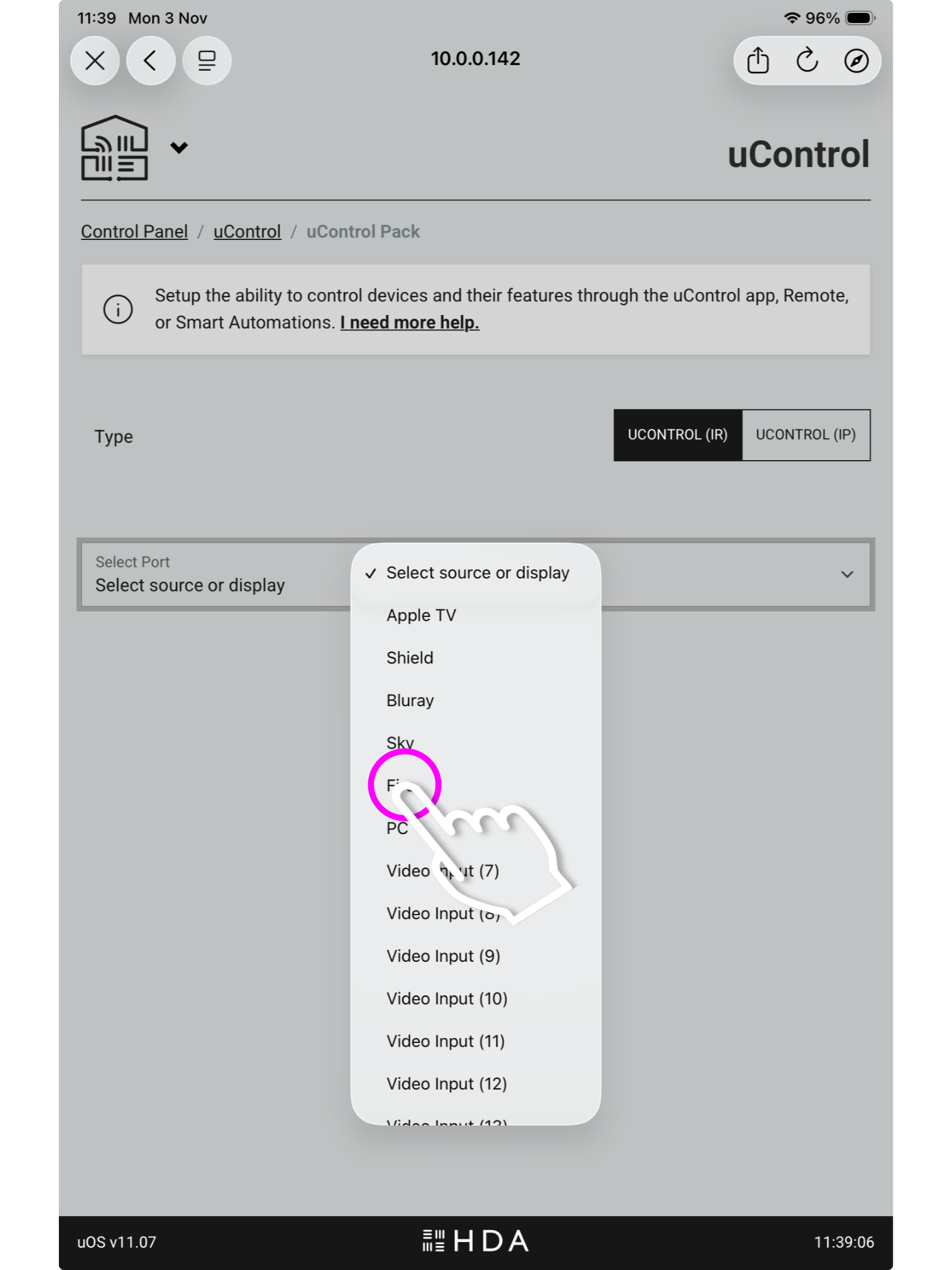
    image 6-6
    You may have labelled your ports after the sources plugged into the HDA device in the setup like above, or they may remain named numerically.

    7. Pack Information

    Once you have chosen the port you need to select the device type and its manufacturer then press install.
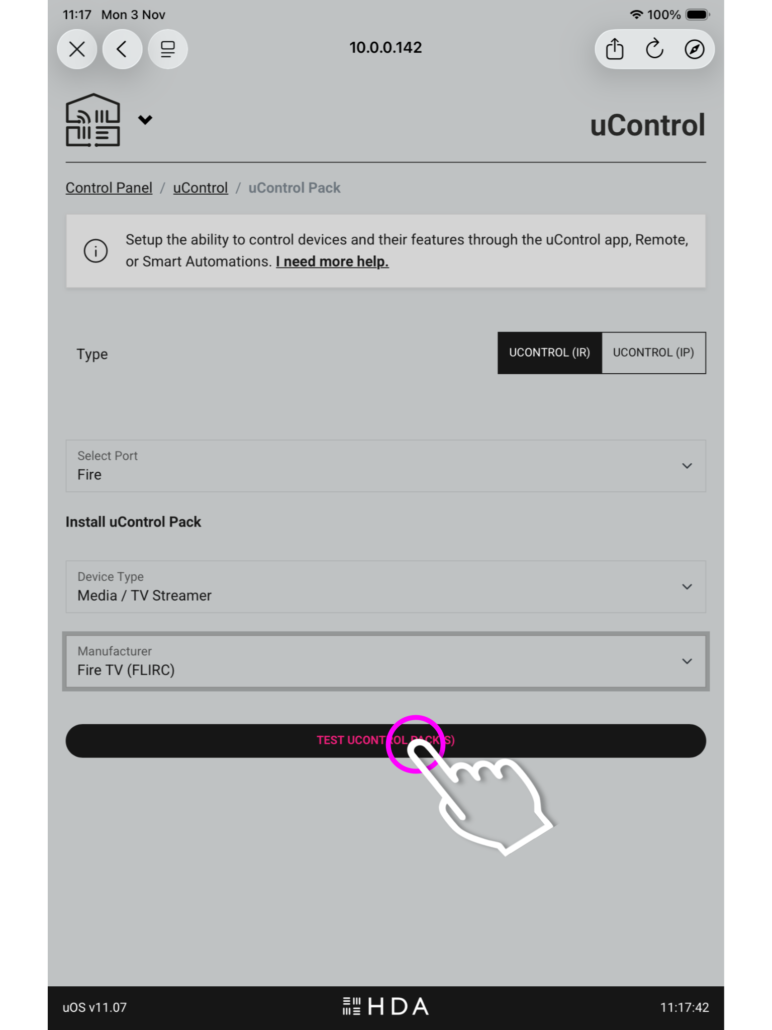
    In the top right you will see the option to switch between IR and IP packs.

    8. Testing the pack

    The last step is to test the commands to make sure you have the correct pack installed, if you get a response press install.
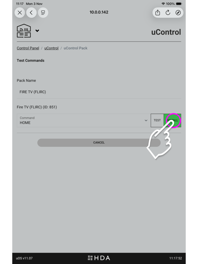
    image 7
    If you do not see a response, ensure you have the IR trasnmitter plugged into the correct “Source IR Out” port and have the bud itself covering the IR window of the source device.

    9. Using the pack in uControl Homepage

    You will see your available sources at the top of the uControl Homepage, and you can use these icons to switch between inputs.
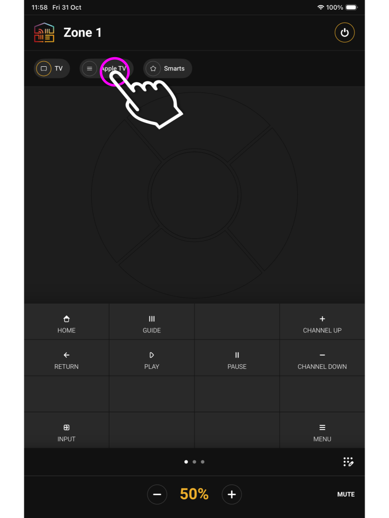
    image 9
    The pack UI will have the buttons which would appear on the remote, along with a gesture box for navigation and volume controls located at the bottom.


    Installing uControl Packs from uControl

    1. Open uControl

    From the main screen navigate to the menu in the top left.
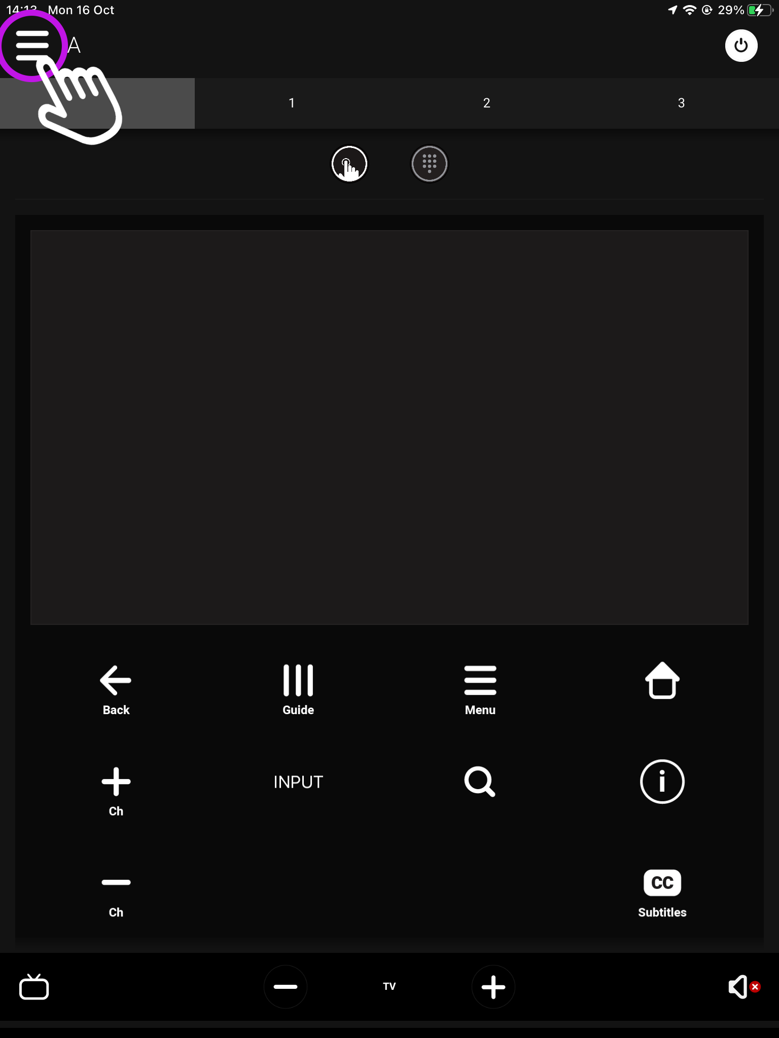
    What you see on the main screen may differ, however, the three lined menu bar will still be there.

    2. Navigate to your settings

    Look for the settings icon located in the bottom left corner.
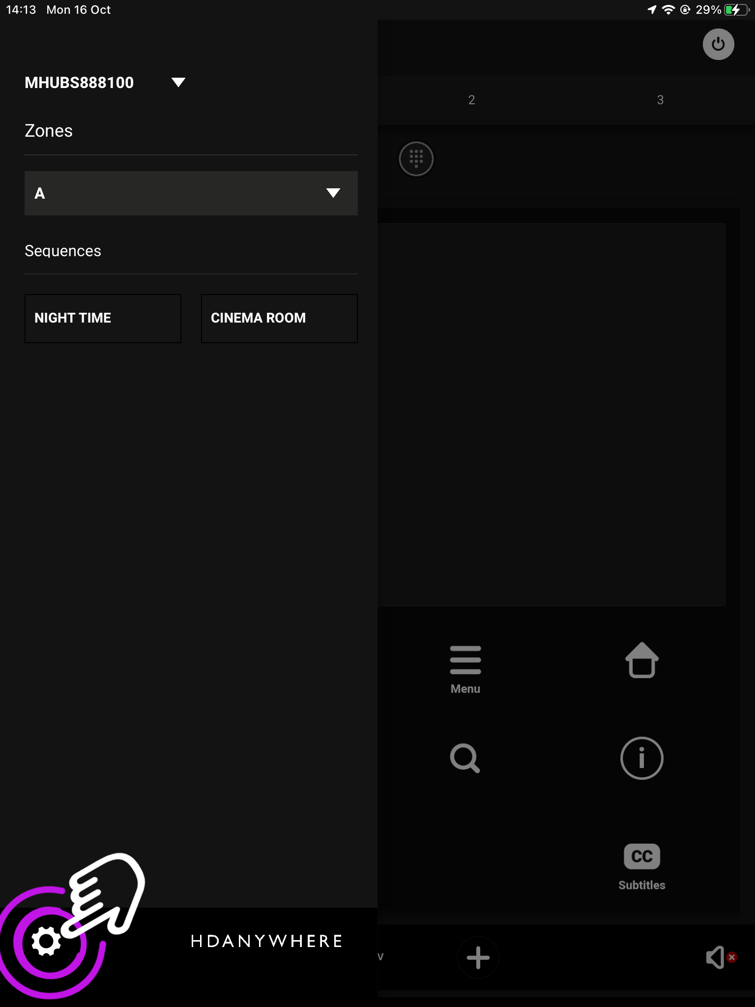
    The icon may vary depending on your mobile devices size, although it will still be in the bottom left corner.

    3. Access System

    From here press Access System.
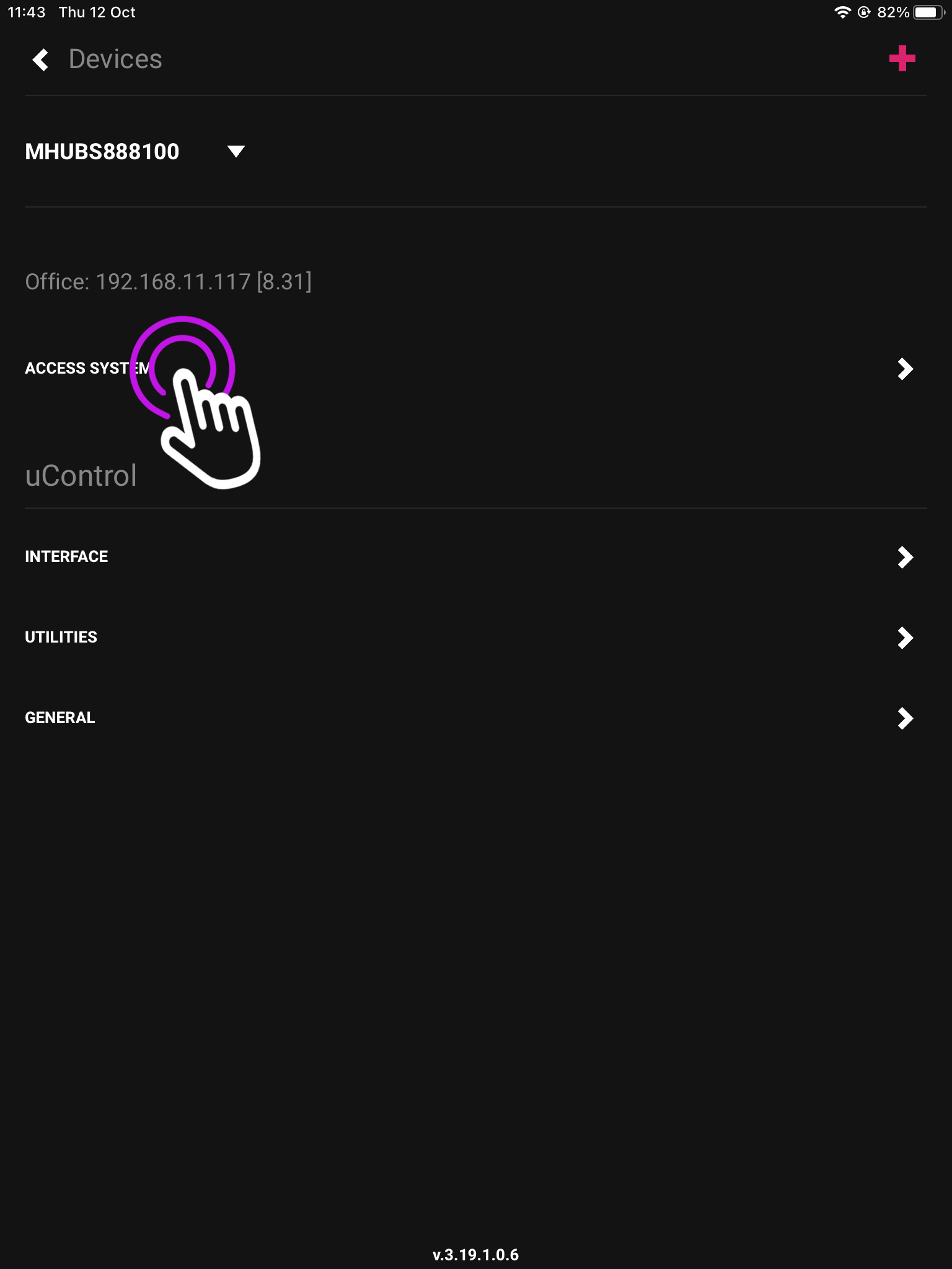
    This is your device page which displays your units model and IP address.

    4. uControl Packs

    In this menu press “Manage uControl Packs”.
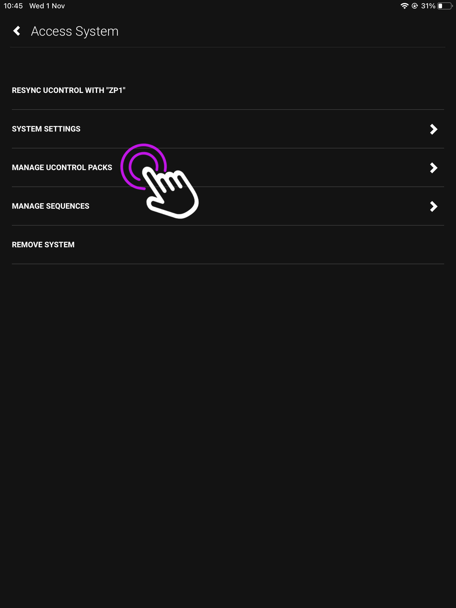
    This will take you to the page where you can download IR and IP packs, and also create IP connections for integrating 3rd party controllers.

    5. Add New

    Now we are in uOS press Add New and a pop up window will appear, press uControl Pack.
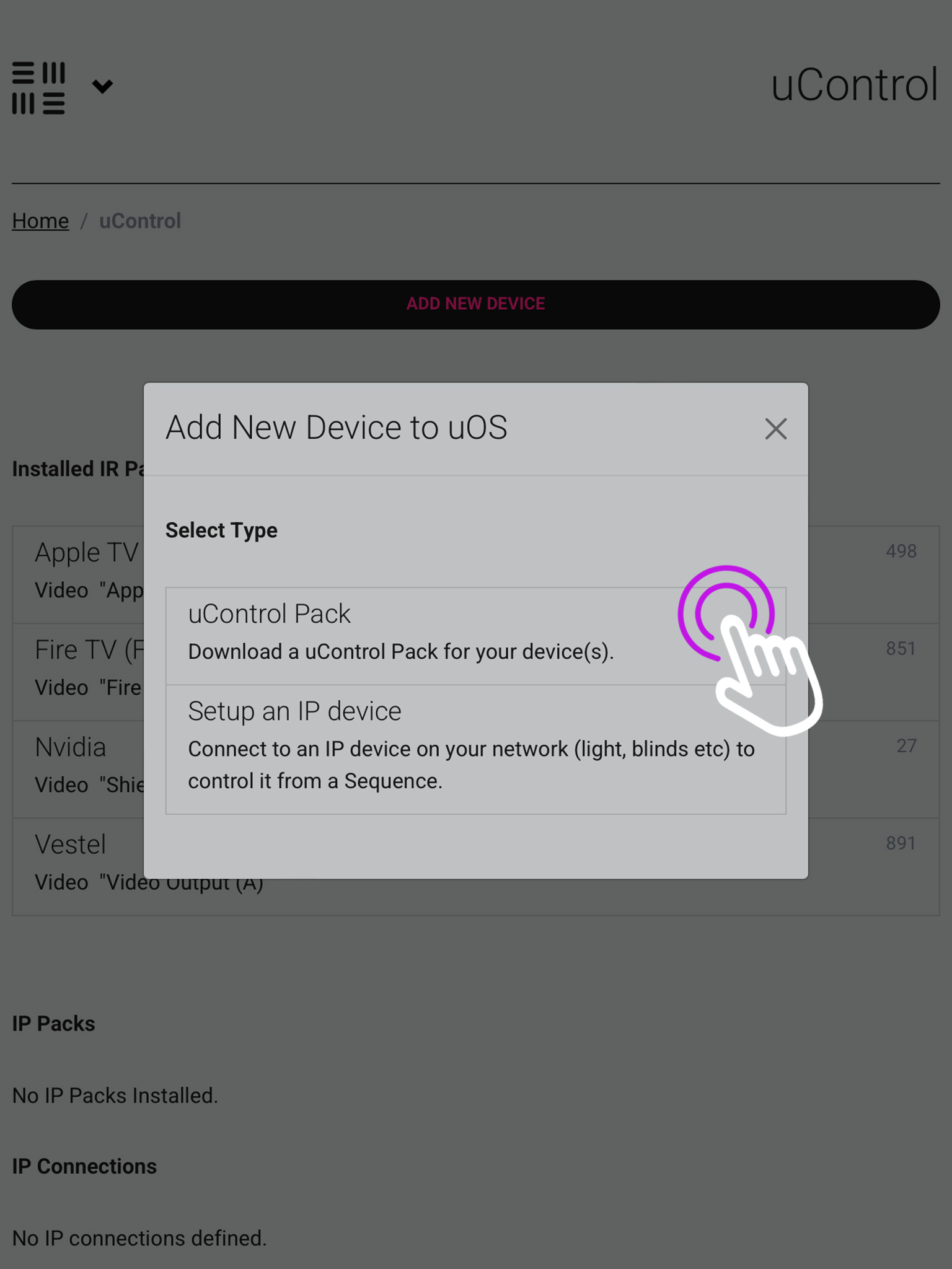
    The below option (Setup an IP device), is for integrating third party controllers to be controlled by uOS.

    6. Port Select

    You must now select if you’re installing a pack for a source device or a display/output.
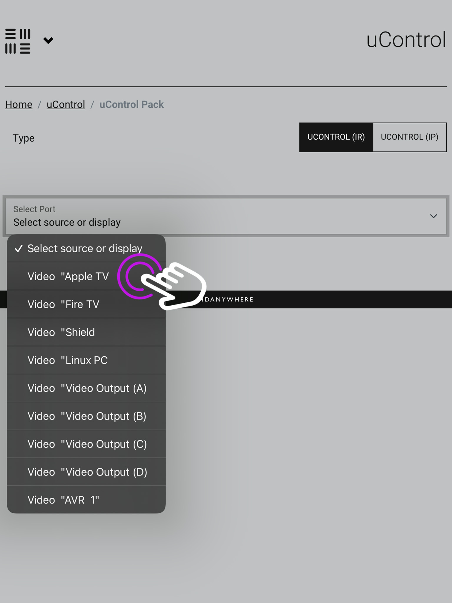
    You may have labelled your ports after the sources plugged into the HDA device in the setup like above, or they may remain named numerically.

    7. Pack Information

    Once you have chosen the port you need to select the device type, its manufacturer and model then press install.
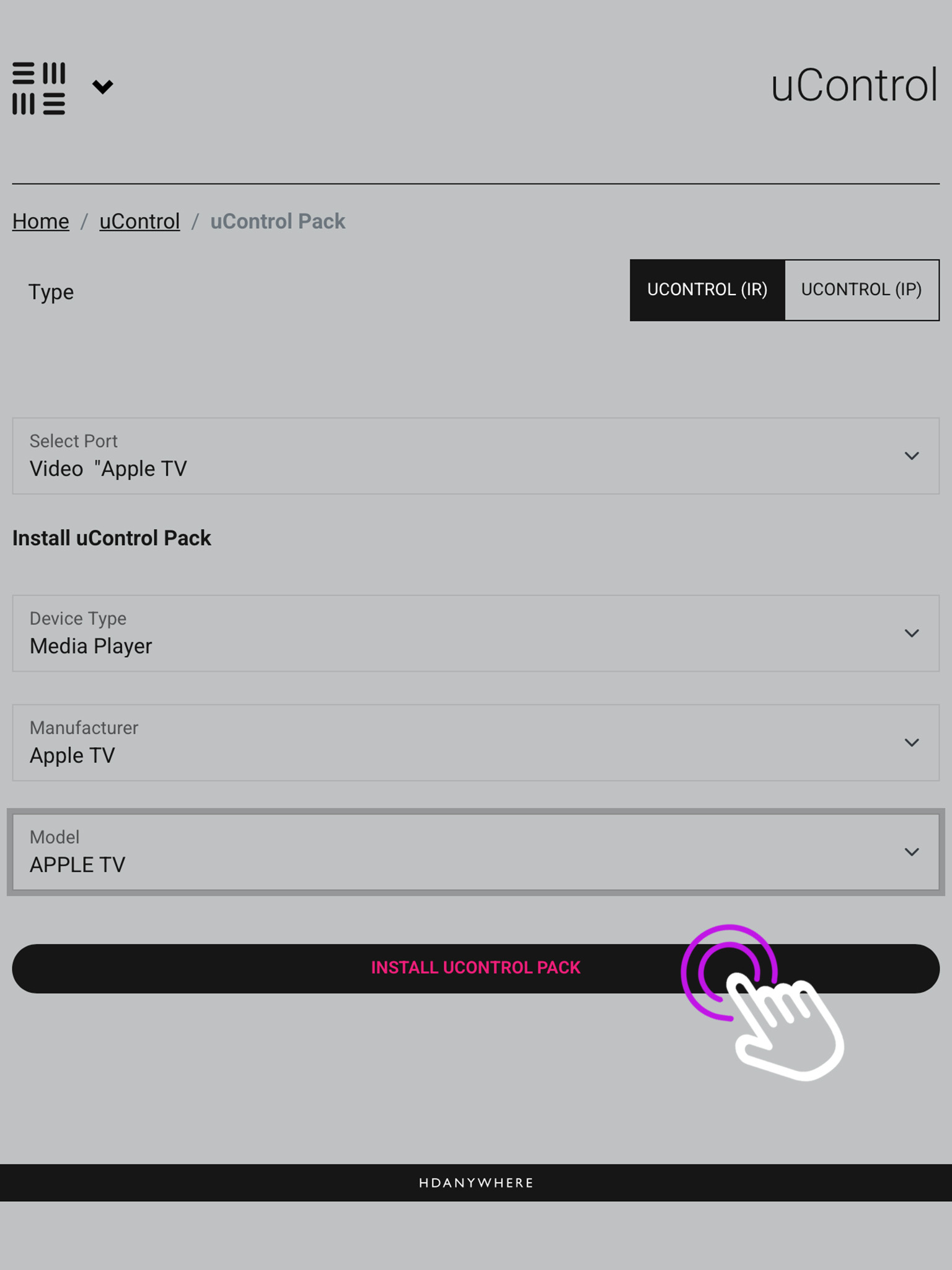
    In the top right you will see the option to switch between IR and IP packs.

    8. Testing the pack

    The last step is to test the commands to make sure you have the correct pack installed, if you get a response press install.
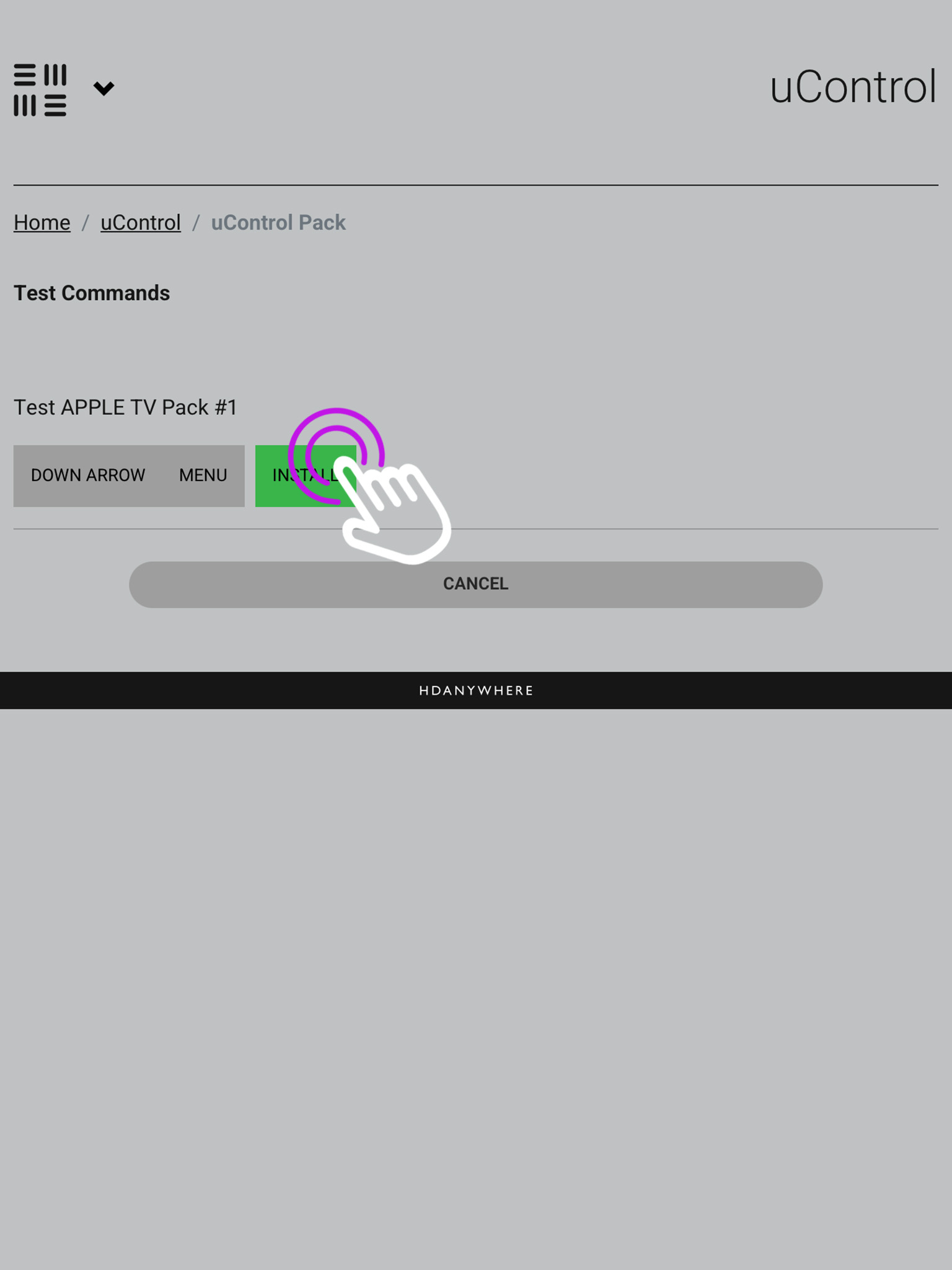
    If you do not see a response, ensure you have the IR trasnmitter plugged into the correct “Source IR Out” port and have the bud itself covering the IR window of the source device.

    9. Using the pack in uControl Homepage

    You will see your available sources at the top of the uControl Homepage, and you can use these icons to switch between inputs.
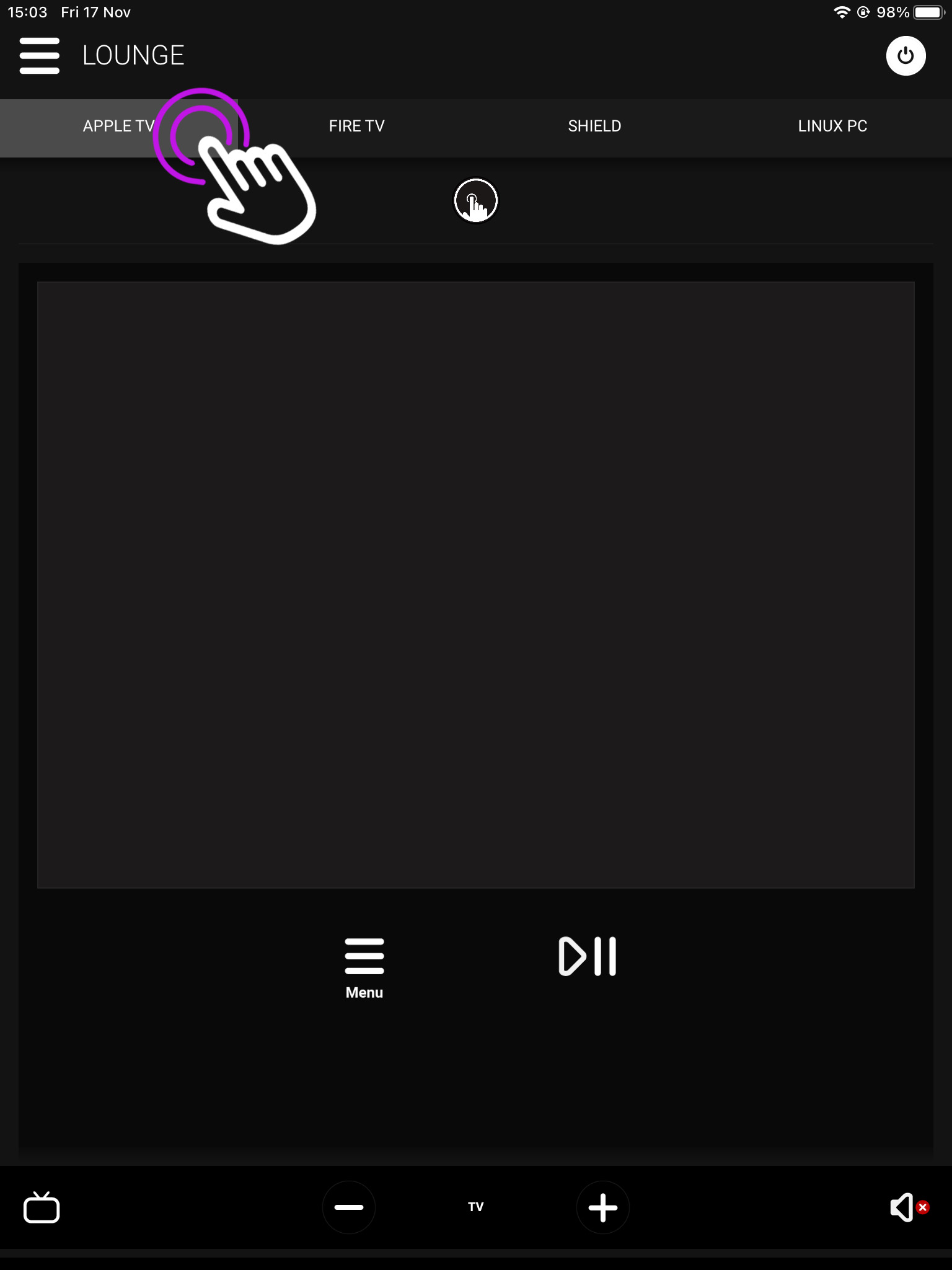
    The pack UI will have the buttons which would appear on the remote, along with a gesture box for navigation and volume controls located at the bottom.

  • Modular Error Codes (4×4 and 8×8)

    Error Code Description
    1001 Corrupt Service Card – Replace the SDCard or format and re-create
    1002 Insert valid SDCard – No card detected or installed in the unit
    1003 Write Protect Mode – SDCard is in write protect mode
    1004 System Failure – MatrixOS is missing from the system and needs to be installed – i.e. rebuild the SDCard
    1005 Insert Service Card – Insert an SDCard with a valid matrix OS firmware image
    1006 Update failed – No firmware image found
    1007 Update failed – Firmware image is corrupt or invalid
    1008 Update failed – Firmware image is too large for the system.
    1009 Remove service card – A bulk update card is installed and the update is complete, ready for a normal service card.
    1010 Onscreen message varies – The unit update has failed and will be showing where internally in the unit it has failed.
    1011 Update failed writing to flash. A critical error and process was stopped
    1012 Communication Fault – The system cannot bring up internal communication bus and is unable to proceed
    1013 Module Fault – Comes with specified module number
    1014 System Fault – An internal IC has failed, indicated by the extended error code
    1015 Input hotplug fault. Unable to enable the hot plug 5V voltage for one or more input modules
    1016 EDID Setup Fault – The system cannot bring up the EDID mixing routines
    1017 Communication fault – The system cannot bring up the 5V I2C communication line
    1018 IR Mux fault – The system cannot bring up the IR Mux subsystem
    1019 IR Capture fault – The system cannot bring up the IR capture subsystem
    1020 Local Network Failure – Unable to ping the local gateway
    1021 Remote Net Failure – Unable to ping DNS servers
    1022 Module Power Fault – The system reports that one of the voltages used to power modules is not functioning correctly
    1023 Network HW Fault – The network hardware has a hardware fault
    1024 Network HW Fault – EDID Read Failure – the system has failed to read the EDID from a connected device
    1025 Network HW Fault – Filesystem Fault – The system has an issue reading from the SDCard
    1026 Network HW Fault – Invalid update URL – The custom URL for retrieving updates is not valid
    1027 Network HW Fault – Discovery failure – the system has failed to enable its auto discovery feature (SDDP)
    1028 Network HW Fault – Invalid Aux MCU – the Component fitted is incorrect
    1029 Update failed – This version is too old for this part
    1030 Invalid Module – A module is inserted in the wrong port
  • EDID management on MHUB systems


    What is EDID?
    When you connect an HDMI source such as Sky Q directly to a display, the HDMI cable will send a data exchange between the two devices before they both agree to serve and display a picture. This process is called the handshake. One component of that handshake is called EDID and this is where your display tells the Sky Q what its visual and audio capabilities are (resolution, refresh rate, stereo or multi-channel audio, HDR, etc, etc). In return, Sky Q will choose a picture format that best fits that profile and output something specifically for that display only.

    A source device can only output a single format, so you could not get it to output a 4K signal and a 1080p signal simultaneously. It has to be one or the other.

    EDID in MHUB​
    If a device sits in between the source and display (like MHUB) then it must broker that handshake. The complexity comes when you have multiple displays of varying specifications connected to your system. For example, you may have 4K, 1080p, and 1080i capable displays, each with varying audio support. These displays send EDID information back to MHUB. If no EDID profile has been configured in the MHUB system the source will output the lowest common denominator, basically the spec of the least capable display.

    This is where EDID management within the MHUB comes into play. You can set a fixed profile that is passed to the source device directly from the MHUB, overriding any information coming from connected displays. Doing this allows you to fix the output of the source regardless of display(s).

    The benefit of this would be if you wanted your source device to always output a fixed signal, such as 3840×2160(4k) with 5.1 audio, setting this on the MHUB will ensure that will be what the source outputs.

    However, if any display is incapable of receiving the fixed video and audio output you could be left with no video output/audio on those displays unless your MHUB supports video downscaling

  • Handling Dolby Audio (Atmos) and DTS-HD audio with MHUB

    Using a matrix and providing Dolby Atmos or DTS-HD audio.

    atmos-mhub

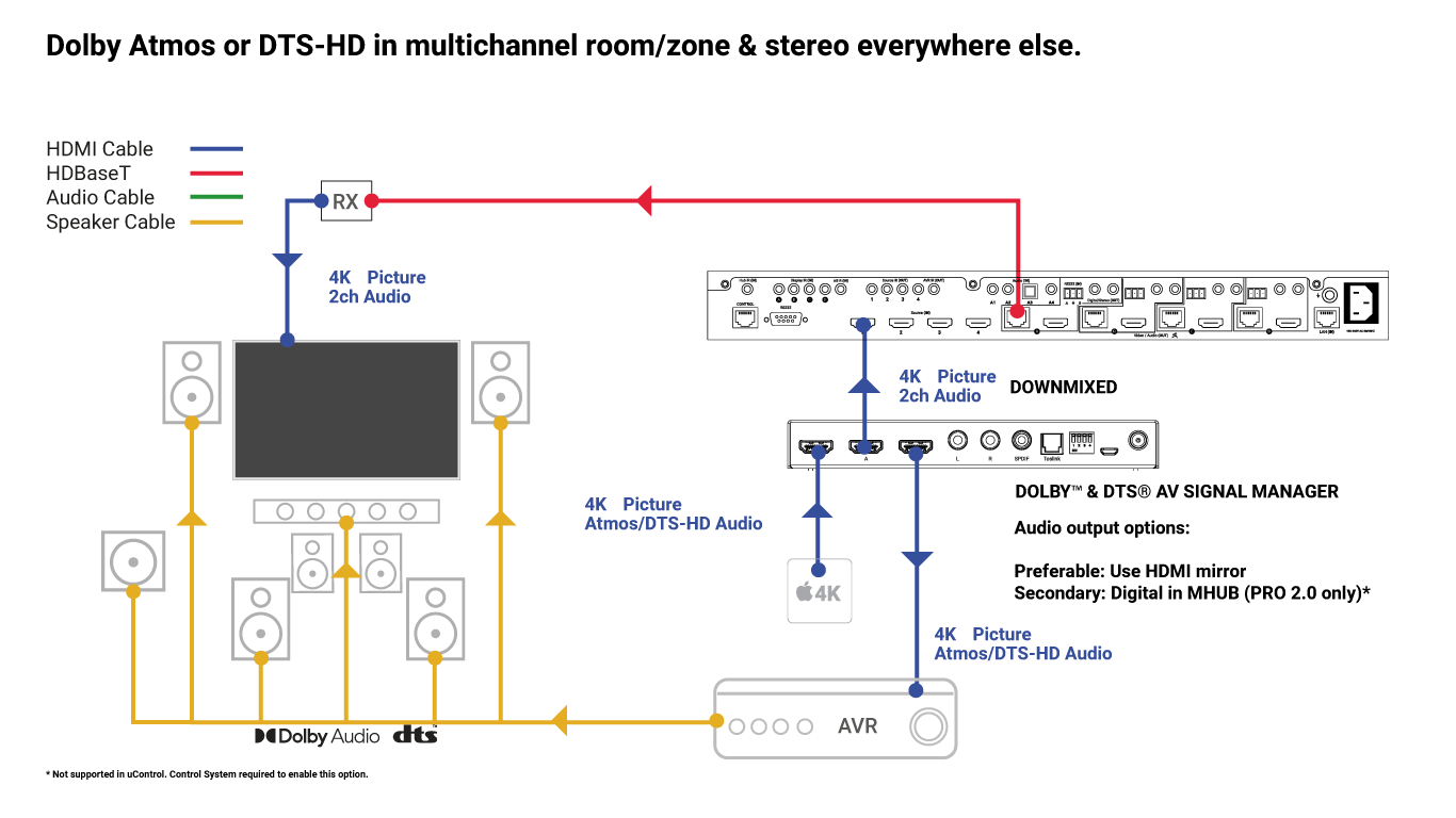
    If you are planning a cinema or media room supplied by MHUB that requires a multichannel audio signal like Dolby Atmos or DTS-HD then you will need additional hardware to achieve this result.

    Why do I need additional hardware and what does it do?

    In order to enjoy Dolby or DTS audio in a cinema or media room you will need to instruct your source device (AppleTV / Bluray / Set top box etc) to output its audio in Dolby Atmos or DTS-HD only.

    If all the zones in your property can accept a multichannel Dolby or DTS signal then you will have no problem but the chances are that the rest of the rooms in the property will just have a standard TV with a left and right speaker only – think of a kitchen TV display or a TV in a kids room.

    You therefore need a device that sits in-line (between) your HDMI video source and the MHUB that does the following important things:

    1. Sends an untouched signal from your HDMI source to your AVR (as if they were connected directly to one another) to provide it with Atmos or DTS-HD audio and…
    2. Split the signal and ‘downmix’ it so all those channels of audio are mixed into a left and right only for all other displays that the MHUB serves.

    What is it called?

    The device that you need is called the Dolby™ & DTS® AV Signal Manager.

    What devices does it work with?

    It will work with MHUBs and XTND hardware which feature HDMI mirrored outputs.

  • Controlling Philips Hue lighting from uOS

    This guide explains how to pull data from the Philips API so you can control it directly from uOS, uControl App and uControl Remote.

    Philips Hue Lighting in uOS

    What this guide will cover:

    1. How to gather information about your lights and use this to set their states.
    2. How to create a Philips Hue API so that you can control any light in the property.
    3. How to add that API into uOS

    Important: you must have a developers account first

    Before you can access the full Philips Hue API you must have made a Philips Hue Developer account.

    Retrieving the IP address

    There are a few ways you can get the IP address of your Philips Hue device:

    1. Use a network scanner app like Fing to find Philips Hue on your network.
    2. Use Philips Hue broker server discovery process.
    3. Log into your wireless router and look for Philips Hue in the DHCP table.
    4. The Philips Hue app – Start the Hue app and push link to connect to the bridge. Use the app to find the bridge and try controlling lights to ensure that everything is working. Then, go to the settings menu in the app, go to Hue Bridges, select your bridge and then the IP address of the bridge will be revealed.

    Generating an access token

    For the purposes of this guide we are going to pretend that your Philips Hue bridge is on IP address 192.168.1.15 and your uOS device (MHUB, MZMA or Zone Processor) is on 192.168.1.196. We will use this to illustrate all examples moving forward.

    Firstly, we need to make an access token so you can make changes to the lighting.

    To start this process, head over to the web browser API by typing in the command below with the IP address specific to your Philips Hue bridge.

    http://192.168.1.15/debug/clip.html

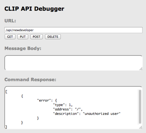
    Once loaded, you should see a grey “CLIP API Debugger” extension pop up, you then need to type /api/newdeveloper and click GET. You will get a reply in the command response which will state you’re an unauthorised user.

    CLIP API

    We now need to use the randomly generated username that the bridge creates for you. To incorporate this, do the following:

    1. Start off by typing /api into the URL.
    2. Then go ahead and type {"devicetype":"my_hue_app#iphone peter"} into the message body, we have used Peter as our example but your username will most likely be different so change it accordingly.
    3. Lastly, select your method as POST.
    BRIDGE

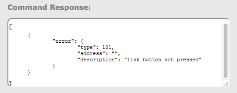
    After clicking POST you should get an error response telling you to press the link button, make sure to go press it on the bridge and then click POST again on the API. This is a security step which stops other people from accessing your lights.

    You should then be given your access code which will look similar to the one below, make sure you hold onto this as it will be needed for all commands moving forward.

    102ad6f46x253e821gcfr9ef1h07j10f

    Now we have our acces token and you’re familiar with using the API, we can start controlling our lights. Watch the slideshow to see how to do execute different commands and what they do.

    Testing your APIs

    As Philips API commands require a command for the URL and also the message body, you will have to test if they’re working on the Clip API Debugger program. If they work, they are ready to be added into uOS!

    If it doesn’t work then try the following:

    • Make sure the IP address is correct.
    • Make sure that you do not have any typos.
    • Ensure that your IDs are correct and that you’re observing a light in the correct room and location.
    • Make sure that the structure of the API matches our example no spaces, no special characters, data is in the correct case (often lowercase).

    How to add your APIs into uControl

    Need more help with the API? Get in touch.

    All HDA staff are able to help with any API questions you might have including any advanced features. Get in touch for help or assistance.

  • Using Flirc with NVIDIA Shield for use with uControl

    Some devices no longer have built in IR receivers. To enable them to be used with the uControl app you can add a third party device called FLIRC. This connects to a source device via USB and turns IR codes into control commands the source device recognises.

    The Flirc device can be found here – Flirc

    Install the Flirc software on your computer, and install this profile onto your laptop/PC – NVIDIA Shield

    Load up the Flirc software and in the top left click File, and then Load Configuration and choose the NVIDIA Shield profile you have just downloaded

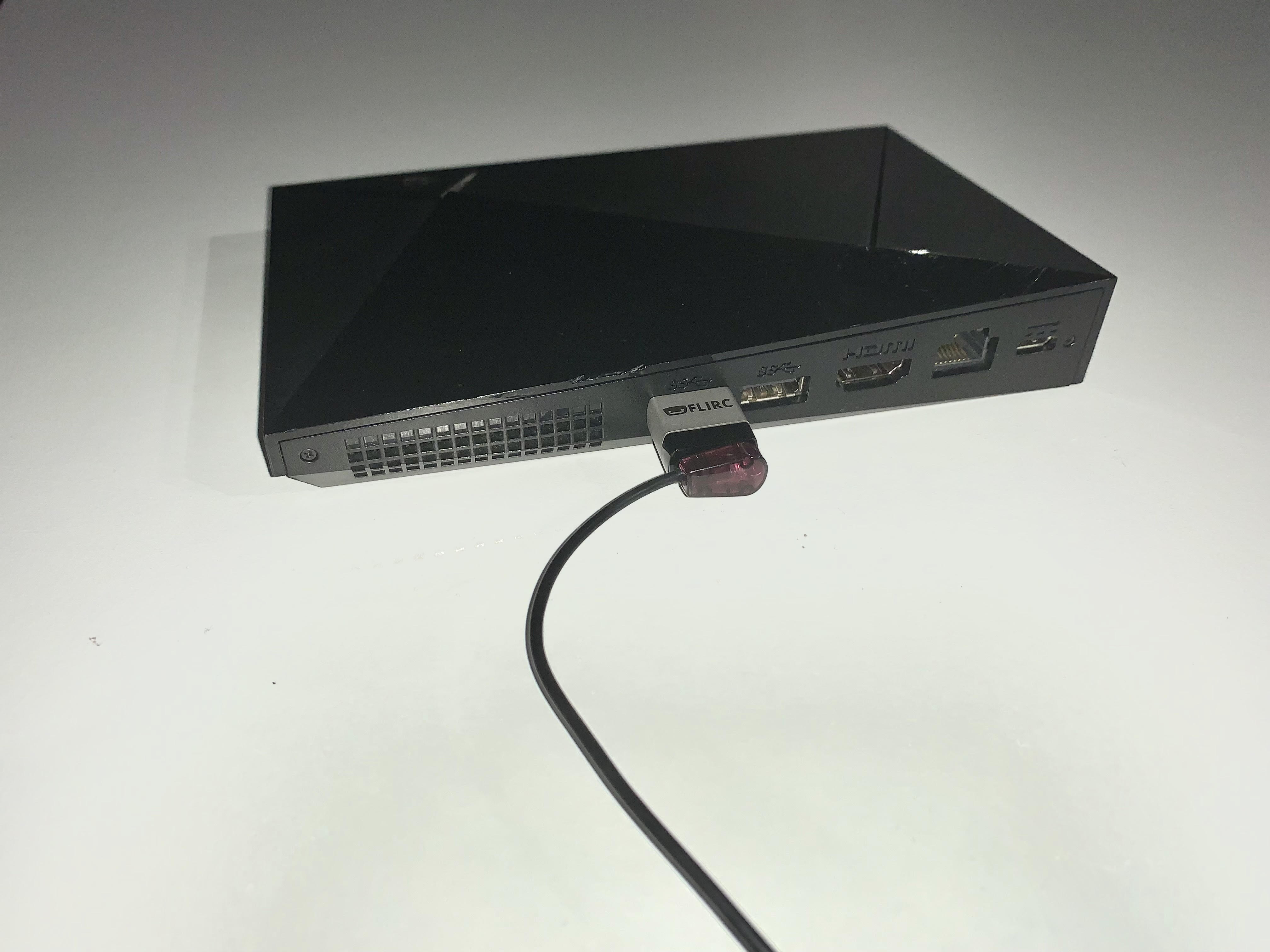
    Remove your Flirc from the laptop/PC and connect it to the female USB port on the back of your NVIDIA Shield. Next place the IR transmitter from you HDANYWHERE device on or near to the Flirc.


      update-mos

    Once this is done you can install the NVIDIA Shield IR pack and control your NVIDIA device with uControl.

  • HDBaseT compatibility with Panasonic CX/CS series

    blog

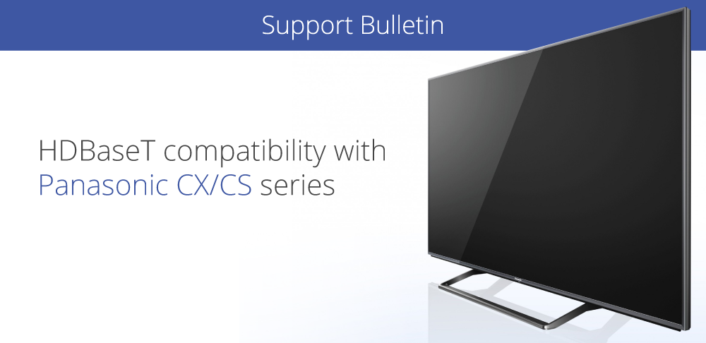
    The recent release of Panasonic’s new CX/CS HDTVs feature no support for the HDBaseT transmission technology found in HDanywhere’s multiroom matrices (Modular 4×4 and 8×8 / mHub 4K / 100m Pro Extender).

    This software incompatibility caused these displays to be unable to display picture from HDanywhere products. Please note that this only affects NEW Panasonic CX/CS range displays.

    Yesterday, Panasonic released firmware updates resolving this issue. There is now full compatibility between HDanywhere products and Panasonics entire range of displays.

    A Quick tip for updating the TVs on a network: if you select update firmware in the normal way, it will probably say that it’s already up to date. You need to go to apps then select Netflix, and that will force it to check the update server.

    If your TV isn’t downloading the update automatically you can manually update it.

    For CX you need version 3.206 or higher and for CS you need 3.014 and up.

  • MHUB-OS 8 first boot process

    The first boot process for MHUB-OS has remained largely unchanged with the exception of zones.

    The slideshow below walks you through the steps within MHUB’s first boot process and how to setup zones to refect the different rooms or areas within you property.

    If you wish to configure a stacked system please watch this video – Creating a MHUB stacked system.

    You should be able to complete the process in under 10 minutes.

    MHUB-OS first boot steps are as follows:

    1. EULA and Privacy policy
    2. Name your MHUB
    3. Name your source devices
    4. Create zones
    5. Assign outputs to zones
    6. Confirm zones
    7. Connect MHUB to HDA Cloud
    8. Complete setup

    HDANYWHERE(HDA) recommends that every MHUB install goes through its first boot process to ensure that the MHUB is setup correctly.

    How long does the process take to complete

    If you have an update to install then then first boot usually take about 10 minutes. If there is no update you can normally finish the entire process and have an operational MHUB system well within 5-7 minutes.

    Yes. You do not need to access MHUB-OS if you don’t want to. But this is only recommended if you intend to control you MHUB via a control system. You will also miss the opportunity to increase your warranty period and open your MHUB to additional features or services.

    I don’t want to use MHUB-OS or go through the first boot process, will MHUB work like a normal?

    Yes. You do not need to access MHUB-OS if you don’t want to. But this is only recommended if you intend to control you MHUB via a control system. You will also miss the opportunity to increase your warranty period and open your MHUB to additional features or services.

    I made a mistake in the first boot process, can I go back or make a change?

    Yes. You can go all the way back to the update step and correct any incorrect information you entered. Alternatively, you can also access MHUB-OS (after you have completed first boot) and change anything then.

  • Sending TV audio from MHUB to in-wall or ceiling speakers using MHUB PRO 2.0 and MHUB AUDIO

    Extracting video audio from MHUB and sending it to speakers

    Today’s TVs are very thin with the latest models able to be rolled away into a box! A thinner TV is lighter, easier to install and generally more pleasing to the eye as these new advancements can radically change how your traditional TV looks or is installed into your property.

    These advancements have reduced the space inside the TV to an absolute minimum and often a causality of this is the internal TV speaker. Speakers are either located on the rear of the panel (leading to muffled audio) or underneath and in many cases can not provide the type of audio amplification to match the large screen sizes found in the marketplace today.

    Soundbars have plugged the gap, but they aren’t the solution.

    Soundbars have plugged this gap as customers try to achieve audio reproduction that matches their picture quality. Whilst a soundbar is a simple solution to the problem it fair to say that it doesn’t present itself as the most elegant in that it’s additional (visible) hardware that you need to add to your AV setup. The soundbar is also tied to the function of the TV; so it’s not very easy to listen to music on the same device, for example.

    De-embed the audio and manage it separately.

    Using MHUB it’s possible to extract the audio that would be sent to your TV – or even the audio generated from your TV apps like Disney+ or Netflix and send that to speakers in your room. Additionally, when the TV is off you can listen to music on the same speakers. If your speakers are embedded in your walls or are in the ceiling then you won’t even notice them, but you’ll hear the difference.

    Watch the setup video instead.

    MHUB PRO 2.0 + MHUB AUDIO: how does it work

    To achieve this you will need to use MHUB PRO 2.0 and MHUB AUDIO operating together as one system which we call V&A (video & audio).

    Download the MHUB (V&A) guide.

    The MHUB PRO 2.0 can de-embed the audio from any video stream or TV app (using ARC) and downmix it into 2 channel stereo. This audio is then fed into the inputs on MHUB AUDIO which manages amplification of that audio. If you have inputs that require amplification then you can stack another MHUB AUDIO (up to three times using uControl) or as many as you want if you’re using a control system.

    We are here to help. Let us know if you have any questions…

    .

    Contacting us is super easy and we respond fast. Let us know if you have any questions about setting up a V&A system.

  • Controlling NETIO power switching from uOS

    This guide explains how to control your NETIO PDU from uOS, uControl App and uControl Remote.

    NETIO API

    NETIO power switching in uOS

    What this guide will cover:

    1. Understanding switching outputs, batches, ports and their status.
    2. How to create a NETIO API so that you can control power in the property.
    3. How to add that API into uOS.

    Important: you must have the IP for NETIO first

    You can get the IP address of your NETIO by:

    • Using a network scanner application like Fing on your mobile phone to scan your network.
    • Log into your wireless router and look up NETIO in the DHCP table.

    For the purposes of this guide we are going to pretend that your NETIO PDU is on IP address 192.168.1.15 and your uOS device (MHUB, MZMA or Zone Processor) is on 192.168.1.196. We will use this to illustrate all examples moving forward.

    NETIO ports are simple, port 1 is equal to 1 (p=1) and port 2 is equal to 2 (p=2) and so on. When typing your commands, make sure to follow this logic.

    What a typical NETIO API looks like

    http://192.168.1.15/netio.cgi?pass=1234abcd&output1=1

    In the example above we are going to send a command to the Netio PDU (at 192.168.1.15) to execute a power switch turning output 1 to ON.

    Understanding what those variables in the API above mean:

    pass=1234abcd
    This is the authentication and is user definable and can be changed to the name of the device owner on the NETIO web UI.

    output=
    This is the command variable(s):

    • 0 – Turn OFF
    • 1 – Turn ON
    • 2 – Short OFF delay (restart)
    • 3 – Short ON delay
    • 4 – Toggle (invert the state)
    • 5 – No change
    • 6 – Ignored

    “&”
    This sign allows you to add parameters to your command, every command must be linked by it.

    Testing your APIs

    We recommend that you test every API before you enter them into uOS. All IP based APIs have different requirements when it comes to testing but the NETIO API is great because it is super simple.

    To test your API, open a web browser and enter the full API in the URL window and hit enter.

    Screenshot-2023-05-12-121405

    If you get a response in the web browser similar to the one below, and you heard the NETIO PDU tick to signify a switch, then you’re good to take this command and put it into uOS:

    #

    If it doesn’t work then try the following:

    • Make sure the IP address is correct.
    • Make sure that you do not have any typos.
    • Ensure that your IDs are correct and that you’re observing the correct PDU switch.
    • Make sure that the structure of the API matches our example no spaces, no special characters, data is in the correct case (often lowercase).

    How to add your APIs into uControl

    Need more help with the API? Get in touch.

    All HDA staff are able to help with any API questions you might have including any advanced features. Get in touch for help or assistance.