Below is a list of three issues which have been reported to HDANYWHERE (HDA) after updating older systems to MHUB-OS 8 (MOS 8). If you have encountered any of these problems then you will find a solution below. If your issue is not shown below then contact the HDA support team via email on – support@hdanywhere.com.
1.
I’ve clicked the update from within MHUB-OS and now appear to be stuck on an update page and cannot access any other MHUB-OS page.
This error can occur when MHUB fails to complete the update process completely. This can be caused by a power outage, multiple sessions of MHUB-OS being open at the same time (browser tabs, app) or network issues as the update is applied to MHUB. This has been patched in version 8.02 of MHUB-OS. However, if you find yourself with a problem like this, you will need to contact HDANYWHERE technical support services by emailing support@hdanywhere.com with the subject line: “Update error code:728” and we will treat this with the highest priority.
2.
I’ve updated to MHUB-OS 8 and when linking to HDA cloud it says there is an error with my serial number.
This error can occur when the MHUB cannot connect with HDA cloud. This can be caused by network issues or power outage. This has been patched in MHUB-OS version 8.02. However, should you find yourself in this situation you can recover the serial number following these steps
Step 1 – Load a web browser on a pc or mac(such as Chrome), and enter the following in to the URL bar [MHUB IP ADDRESS]/diagnostics.php. Then click on “GET SERIAL NUMBER”
Step 2 – Confirm that you want to change the serial number
Step 3 – You will get a notifcation saying that the serial number has been updated, and should notice the serial number is showing in the system information section near the top of the page.
If after using the serial number recovery method above, it still does not appear, you will need to contact HDANYWHERE technical support services by emailing support@hdanywhere.com with the subject line: “Update error code:628”
3.
uControl has updated, when I reconnected to my MHUB all my settings were gone.
This can occur when reconnecting to your MHUB after uControl has updated to version 2 or greater and selecting the incorrect option. When uControl loads you are shown 2 options:
“SETUP A NEW MHUB SYSTEM” – This is used when you are connecting to a brand new or unconfigured MHUB system. If you select this option and have a previously configured system, all user data will be removed requiring the MHUB to be fully reconfigured like a new system.
“CONNECT TO AN EXISTING MHUB SYSTEM” – This is used when you are connecting to a previously configured MHUB system. Existing data will remain untouched, and uControl will sync the data stored. If you were connected with a previous version of uControl this option should be used.
4.
After the update, uControl can not connect to MHUB
HDANYWHERE released an update to uControl and all MHUB systems on Wednesday 10th October 2018. To ensure that your MHUB works correctly both your MHUB and uControl must be on the correct software version.
MHUB / MHUB-OS = version 8 or above
uControl (iOS / Android) = version 2 or above
If you find that one version of uControl can connect to MHUB and the other can not then it is very likely that you did not complete the update to MHUB-OS. As soon as you have run this process then uControl should work on all devices with no issue. For this solution HDANYWHERE are assuming that your system is already in a pre-configured state and that you are wanting to CONNECT TO AN EXISTING SYSTEM.
Once you have the app installed, please load it up and follow the instructions here:
5.
I have a 8×8 or 8×6+2 system and after the update, I lost the ability to control my TVs
If you are able to control your source devices with uControl but can not control your displays then a quick update to your MHUB will resolve this problem. Instructions detailing how to update your MHUB can be found here. Ensure that you use uControl to update your MHUB and do not try to update your system via MHUB-OS.
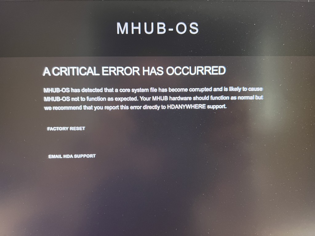
If you notice that uControl has stopped responding or your control system is no longer controlling your MHUB or HDA device and you see a screen similar to the one above when you visit MHUB-OS’ IP address then it is likely that a core file within MHUB has become corrupted or is missing.
Generally, this error affects systems that are on very early versions of MHUB-OS, usually versions 7 or lower (at the time of writing 8.15+ is considered stable). On systems that are already on 8+ it is possible to restore the system sucessfully from a backup but earlier ones will need a HDA technician to check your system to identify the damaged system file and repair it.
If your system is out of warranty then there is a charge of 1 unit for this repair. Please contact HDA first to arrange a technician slot.
Using an Elgato Stream Deck along with an MHUB or Zone Prossesor you can use the Elgato device and our API to send commands to uControl/uOS to control virtually any display, source inputs and lighting control.
MHUB 100A matrices have a USB A port on the front panels in the bottom right corner.
With MHUB PRO models you can enable DHCP from the MENU button on the front panel by holding it down for 3 seconds. For MHUB 100A models you need to follow Guide 1, for newer MHUB U models follow Guide 2 and for older MHUB U (micro USB on front) models use Guide 3.
On Monday 18th of May we rolled out a firmware release to all live Modular 8×8 units. Whilst the update was being delivered to the units we suffered an ISP issue causing the update file to be corrupted in some instances. Most units will repair themselves automatically. If your unit is displaying a ‘1021 cant reach gateway’ error or stuck in a boot loop please follow the instructions below
1. Remove and re-insert the SDCard from the slot on the front by pressing it once to pop it out and press again to pop it back in. This should resolve things in most cases. (This may need to be repeated if the first attempt fails)
2. In more rare cases, it may be that removing all of the cat5 cables from any HDBaseT outputs and then removing and replacing the SDCard is required.
3. In extreme instances, a manual software update is required. To perform this, the SDCard needs to be fully removed from the unit and placed in a Windows based PC. Open The SD Card and remove all files except the ‘SETTINGS.INI’ File. Then file below needs to be downloaded, extracted, then the three files within need to be placed on the root of the 8×8 SDCard. Once there, the card can be inserted back into the 8×8, it should reboot and apply the correct software. Normal operation of the 8×8 will then resume.
If none of the above works, or you require further assistance please contact the technical team via phone or email on 01684576348 & support@hdanywhere.com
Using a Rithum Switch along with an MHUB or Zone Prossesor you can use the device and uControl to execute sequences in uControl/uOS to control your home automation.
IMPORTANT: For the best setup experience, we recommend using a tablet or laptop instead of a smartphone. Using a larger screen makes it easier to navigate the setup process and view all the options clearly.
THIS GUIDE IS FOR uOS 11 AND ABOVE:
This guide is for HDA devices that are operating uOS 11 or above and have completed the First Boot Process. This guide does not apply to ANY hardware running MHUB-OS or uOS devices that are running on version 11 or lower. How to update your system.
Accessing the menu
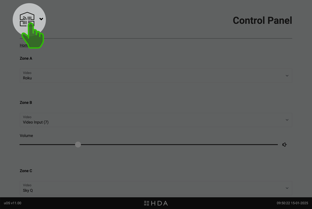
The uOS interface features a hidden dropdown menu that provides access to all system settings. To reveal the menu, simply click on the uControl logo located in the top left corner of the screen.
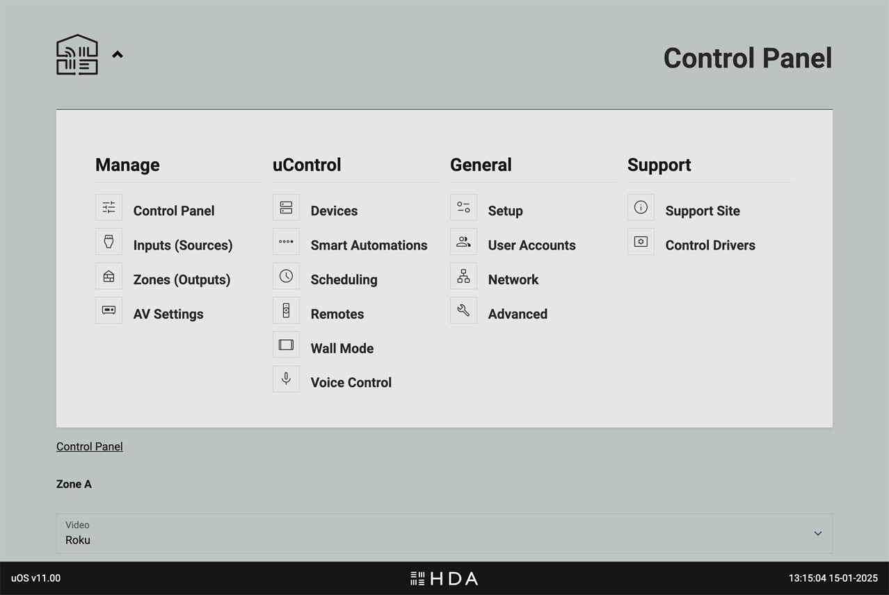
Click or tap on the uControl logo to toggle uOS’ navigation menu.uOS’ navigation menu will appear. Select where you would like to navigate from the options provided or tap on the uControl logo to dismiss the menu.
page_info
Control Panel
Web Interface for direct control of system state.
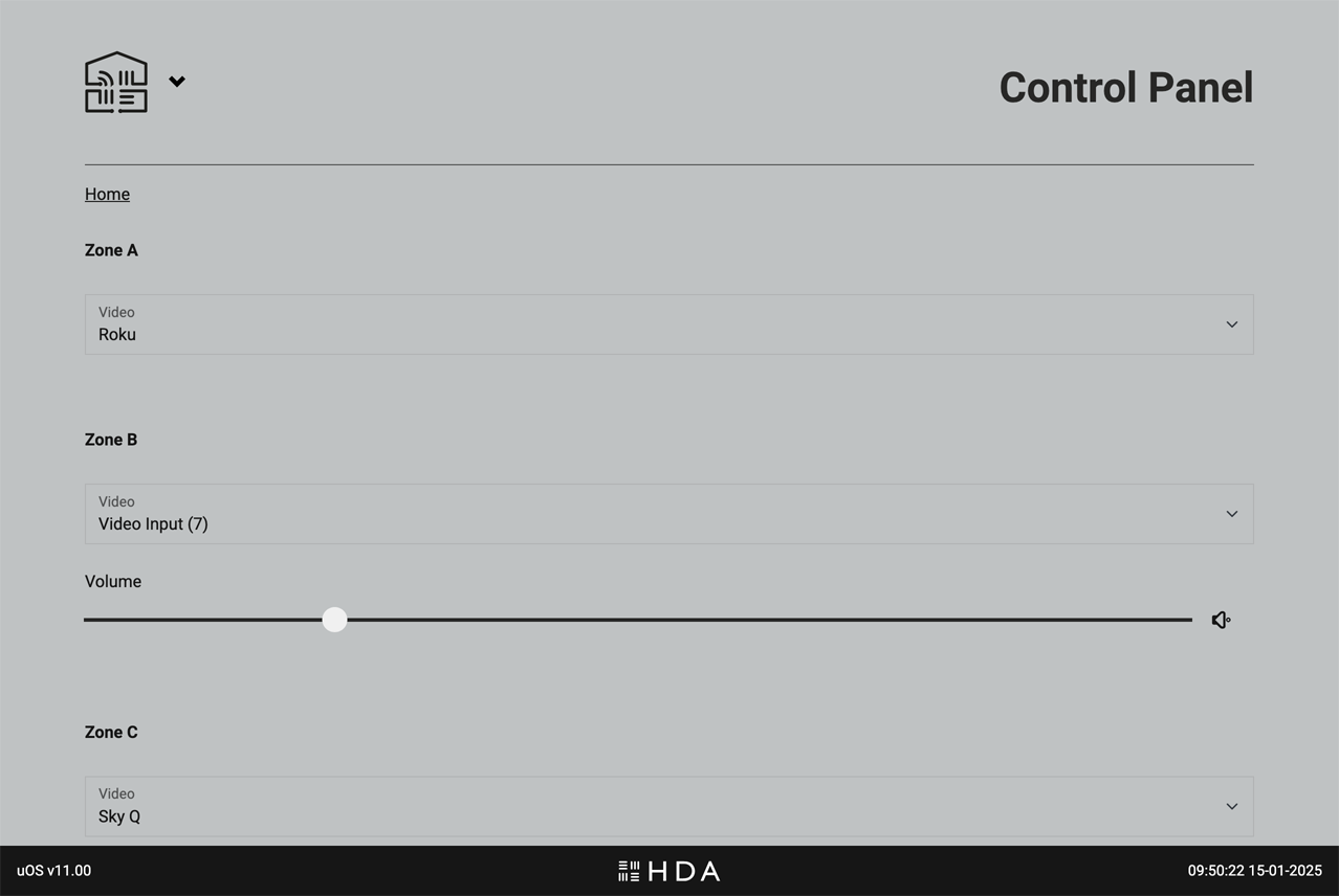
Access direct control of system state settings from the Control Panel. This will be the default page that loads when you visit uOS after you system has completed the First Boot Process.
Gives users direct access to the system state via a web interface, bypassing any other control methods. Control is grouped by Zone and will differ depending on what outputs from your HDA device were assigned to them. For example, if you add a video output and an audio output in a Zone named “Living Room” then uOS will display both video switching, audio switching and (hardware dependent) volume controls in the “Living Room” section of the Control Panel
What can you control?
Source Selection: Choose which video or audio source is routed to the Zone in question.
Volume: If your HDA device supports volume control then a slider and mute controls will appear.
System Power: At the bottom of the page is power control for the entire system. It is recommended to use this control only if you wish to turn the entire system off.
What to do if you can not see any controls on this page or controls do not appear to be working correctly.
Ensure that you have created your Zone and assigned either a video or audio output from your HDA device to it. If you are still experiencing a problem, contact HDA Support.
When to use the Control Panel
The web interface is a valuable troubleshooting and backup tool if you have lost control from your normal control method. If you’re experiencing issues with your HDA system, try controlling it directly through this page.
settings_input_hdmi
Inputs (Sources)
Management of connected AV input devices.
Access direct control of system state settings from the Control Panel. This will be the default page that loads when you visit uOS after you system has been configured.
This page allows you to manage all the AV source devices connected to your HDA system.
Custom Naming: Give your devices meaningful names (e.g., “Blu-ray Player” instead of “Input 1”) for easy identification throughout the system.
Global Visibility: Control which input sources are available system-wide. For example, if you have an 8-input system but only use 5 sources, you can disable the unused inputs (6, 7, and 8) so they appear nowhere in uOS. Important: Hiding an input here makes it unavailable across your entire system, unlike Zone-level visibility settings which only control source visibility of active inputs. This is manaaged from the “Zones” page.
Manage Connections: Tell uOS how multiple HDA devices are connected to one another if you are operating a Stacked System
nest_multi_room
Zones
Manage the Zones in your system.
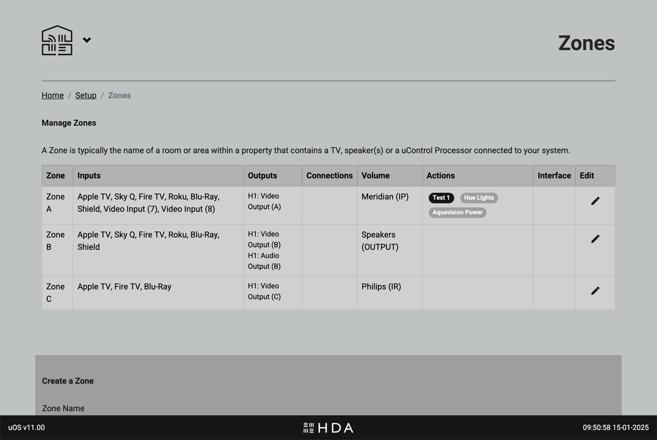
This page is for configuring and customising the Zones within your HDA system. This page provides a clear overview of your entire system from one place.
.
This page is for configuring and customising the Zones within your HDA system. This page provides a clear overview of your entire system from one place.
Key functions on this page
Zone Naming: Personalise your Zones with names that make sense to you (e.g., “Living Room” instead of “Zone 2”).
Source Visibility: Control which AV input sources are available in each Zone. For example, you might want to make the “Blu-ray Player” source available in the “Living Room” but not in the “Kitchen.”
Zone Configuration: Add or remove Zones from your system or change what outputs from your HDA device are assigned to them.
If you are using uControl to control your system, then these Advanced features are also recommended.
Zone (On/Off) Automation: Select what Sequence is assigned to the Zone ON and Zone Off (e.g. TV off, lights off) event.
Default Volume Control:Choose which device from your uControl library has primary control over the Zone’s volume.
Recommendation:Add or remove Zones from your system or change what outputs from your HDA device are assigned to them.
audio_video_receiver
AV Settings
Fine-tune your audio and video settings.
This page allows you to customise advanced audio and video settings for your HDA system to achieve optimal AV performance.
.
This page allows you to customise advanced audio and video settings for your HDA system to achieve optimal performance. This page displays settings specific to your HDA device hardware. If you have a stacked system with multiple HDA devices, you’ll find settings for each device grouped by hardware name and type. This allows for granular control over each device in your system.
Key functions on this page
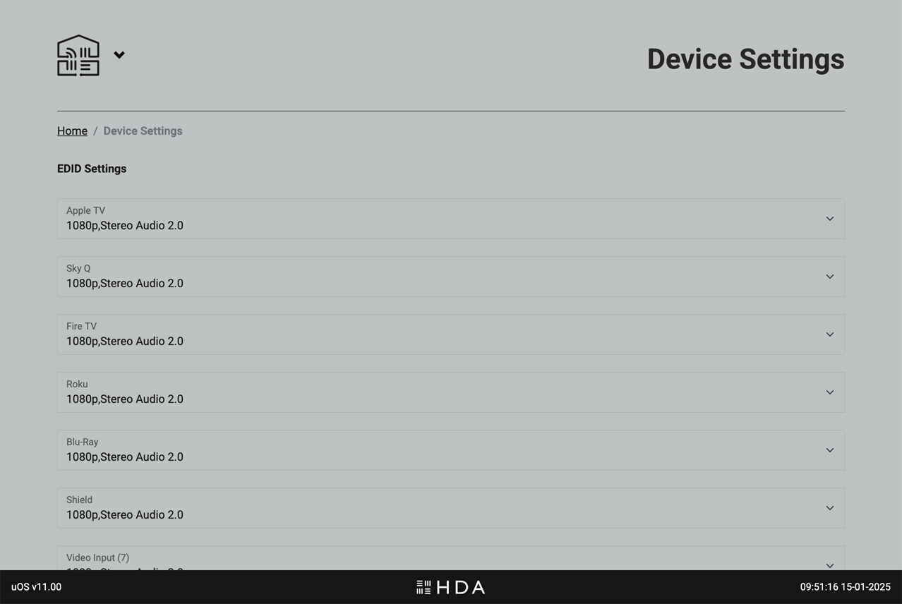
EDID Management: Control how your HDA device communicates with displays to ensure compatibility and optimal resolution.
Video Scaling: Adjust how video content is scaled and displayed on your screens.
Audio Volume Presets:Configure input gain and max volume levels for sources and Zones.
EQ Settings:Fine-tune audio equalisation for specific Zones or outputs.
dns
Devices
Add new devices to uControl or manage how they work.
This page is for managing all devices that can be controlled by uControl.
.
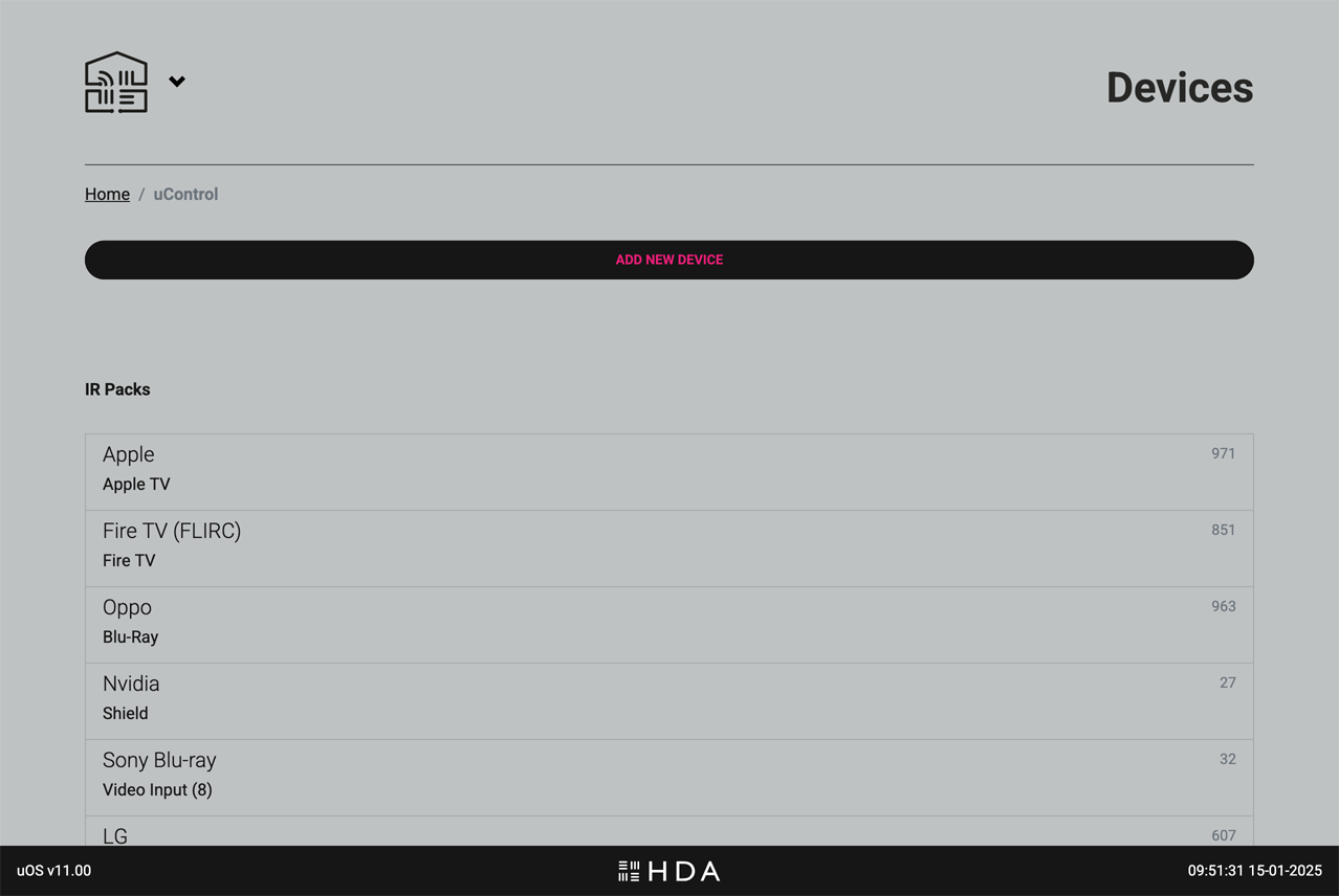
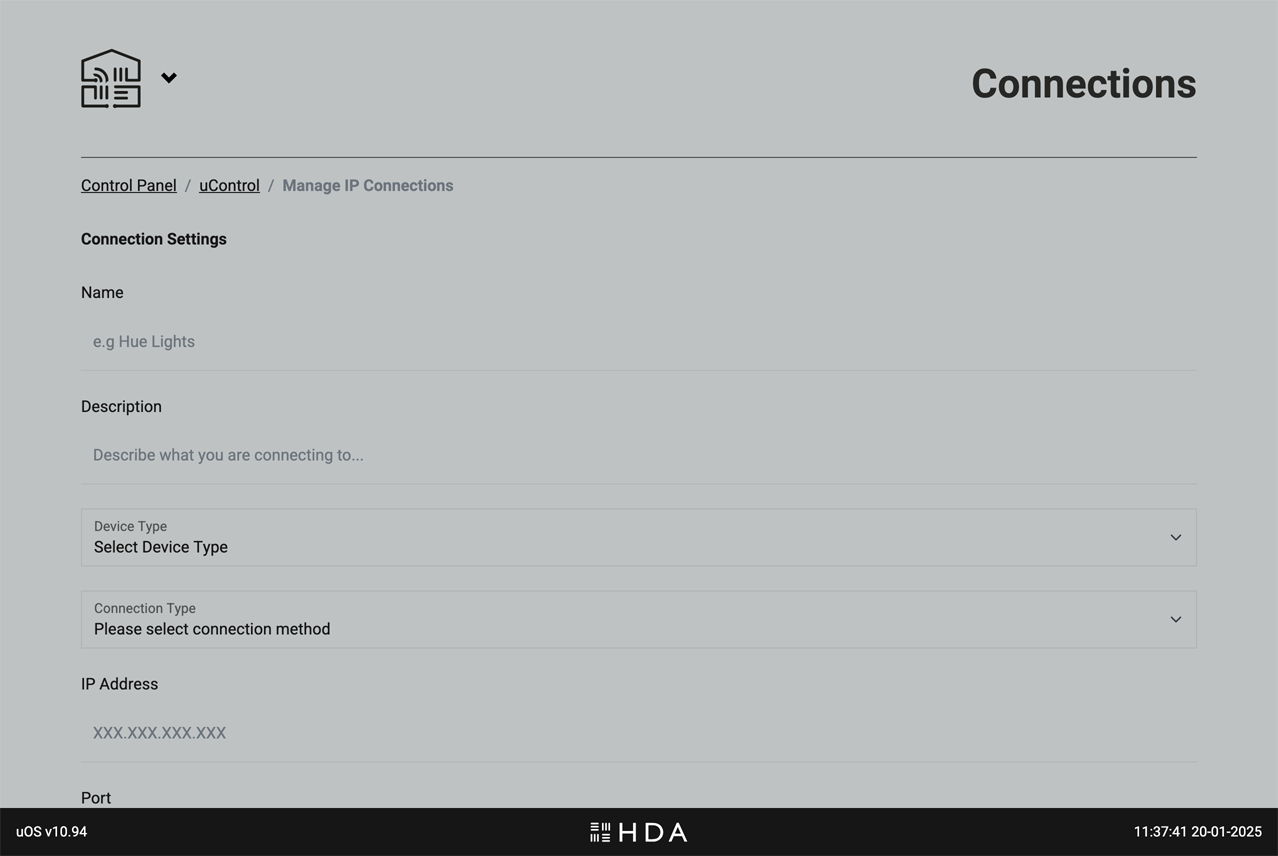
Control your devices and their features seamlessly through the uControl app, a uControl Remote, or Smart Automations. To get started, click or tap on the button labelled “ADD NEW DEVICE” and simply find and install the appropriate uControl pack, driver or establish a uControl IP connection for any Smart Devices (eg, lights, blinds, PDUs etc).
Once installed, all devices that uControl can control will appear here along with any important data such as the current IP address, what input or output the pack is assigned to and the ID.
It is also possible to test CEC commands from the pre-installed uControl CEC pack. This is available at the bottom of the page if your HDA devices supports HDMI-CEC control.
Add device control to uOS
AV Device: select between installing a uControl pack (IR, IP or a Driver) for AV devices like TVs, Blu-ray players, AV receivers, and set-top boxes.
Select “ADD NEW UCONTROL DEVICE” and a window will appear. Select the “uControl Pack” (older uOS versions) or “AV Device” (uOS 11+).
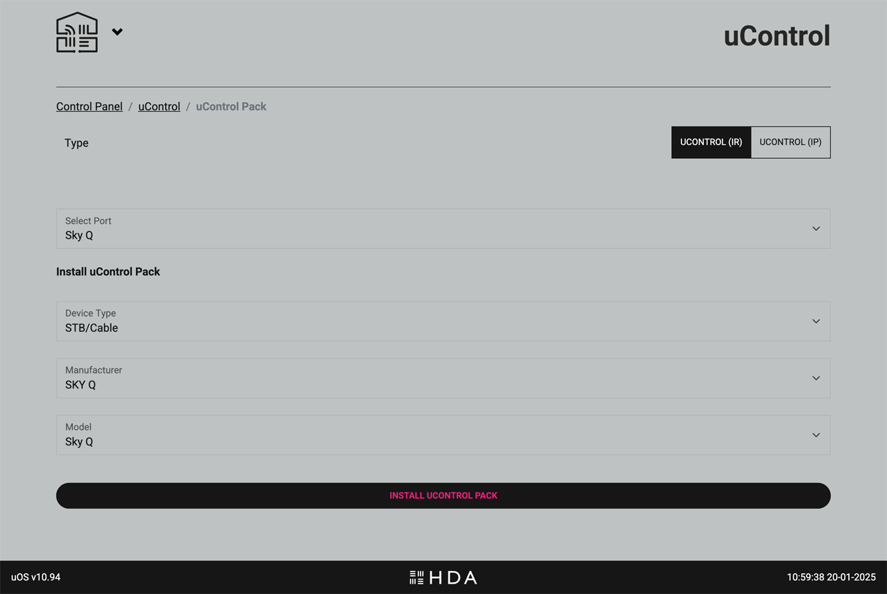
Choose between a uControl (IR or IP) pack for the device and select which input or output it is connected to. The AV device might not be connected to an input or output, and can be assigned to a Zone instead.
Install an AV Device: Select IR, IP or Driver packs to browse and use the options to filter your choice.
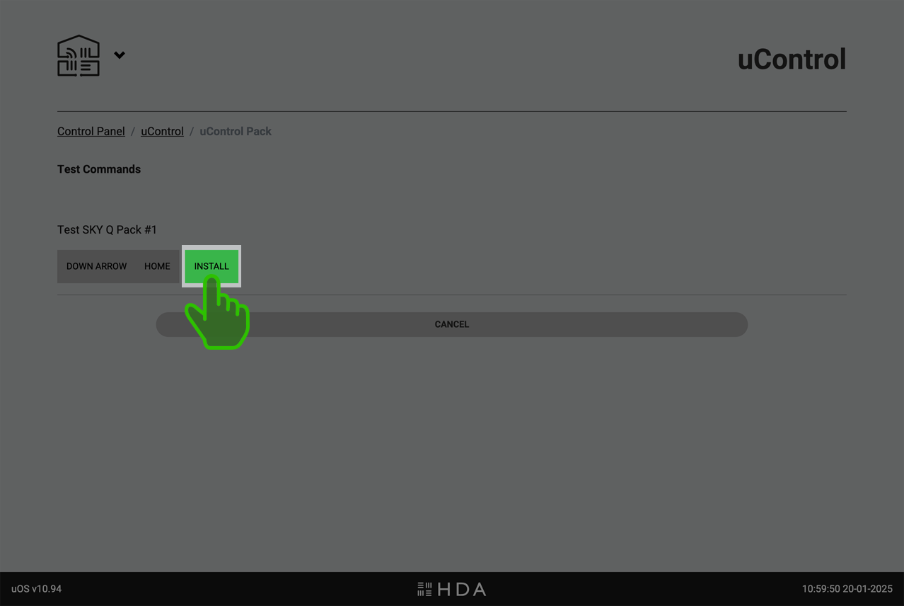
.Install an AV Device: uOS will download the pack and will ask you to test a command. If selected IP, this page will ask you to add connection details (eg IP address) before proceeding. When you have sucessfully tested the pack, continue to compelte installation.
.
Smart Device: For devices that are not AV, you can connect directly to them to control them.
page_control
Smart Automations
Powerful automations to enhance your uControl experience.
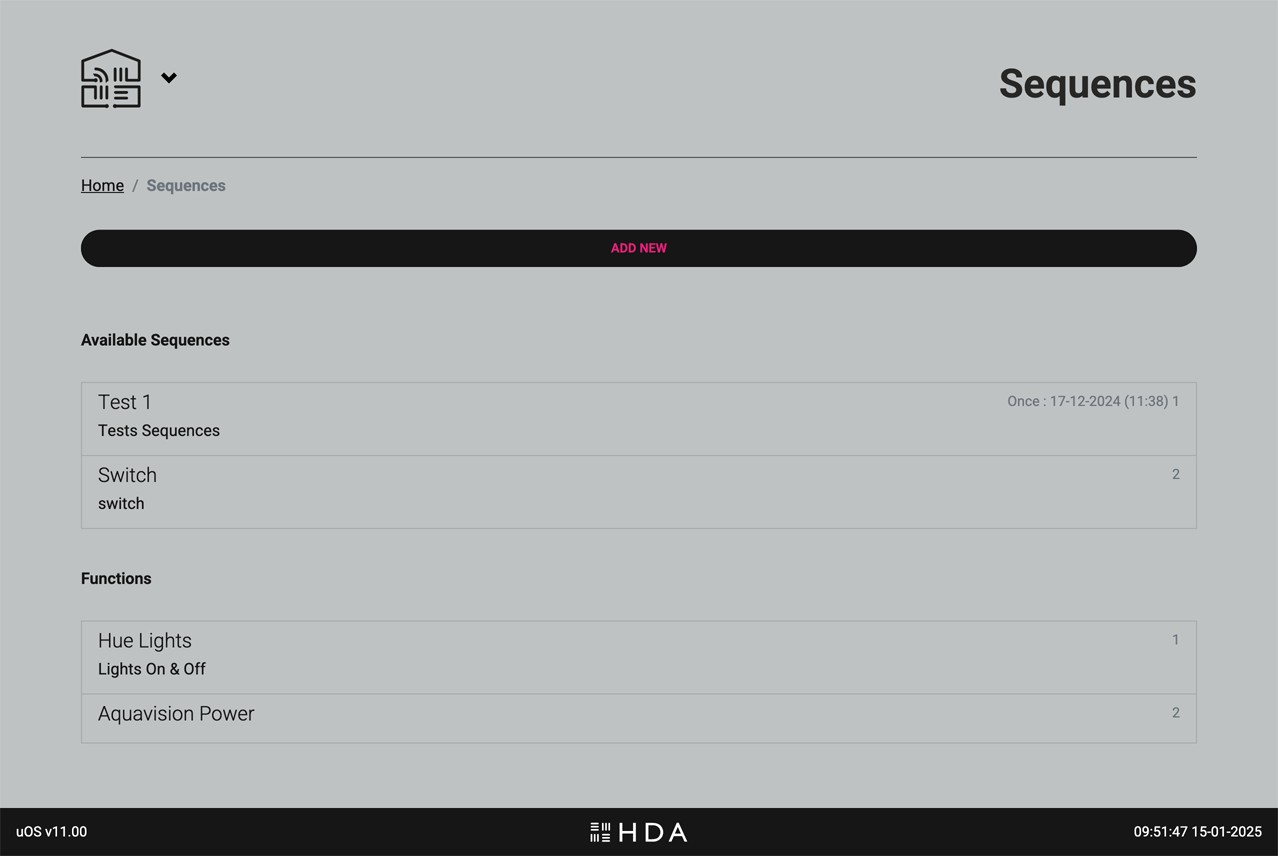
Create Smart Automations called Sequences (a series of commands executed one after another) and add intelligence to them using Functions.
Create powerful automations, called Sequences (a series of commands executed one after another), and add intelligence to them using Functions with “if this, then that” rules to enhance and automate your uControl experience.
You can create Sequences that can turn your HDA device on or off, switch and route inputs or control the volume state in any zone. If you wish to enhance these further with AV device or Smart Device control then ensure you have installed uControl packs for them or have established IP connections before creating your Smart Automations.
Key functions on this page
Sequences: A sequence is a series of commands executed one after another. For example, a “Movie Night” sequence might dim the lights, lower the blinds, turn on the TV, and start your Blu-ray player.
Functions: Functions add intelligence to your automations. They can be custom commands or (“if this, then that”) logical rules. For example, a function could automatically adjust the thermostat when the temperature outside changes or turn on the lights when motion is detected.
schedule
Scheduling
Automate your Smart Automations with Scheduling
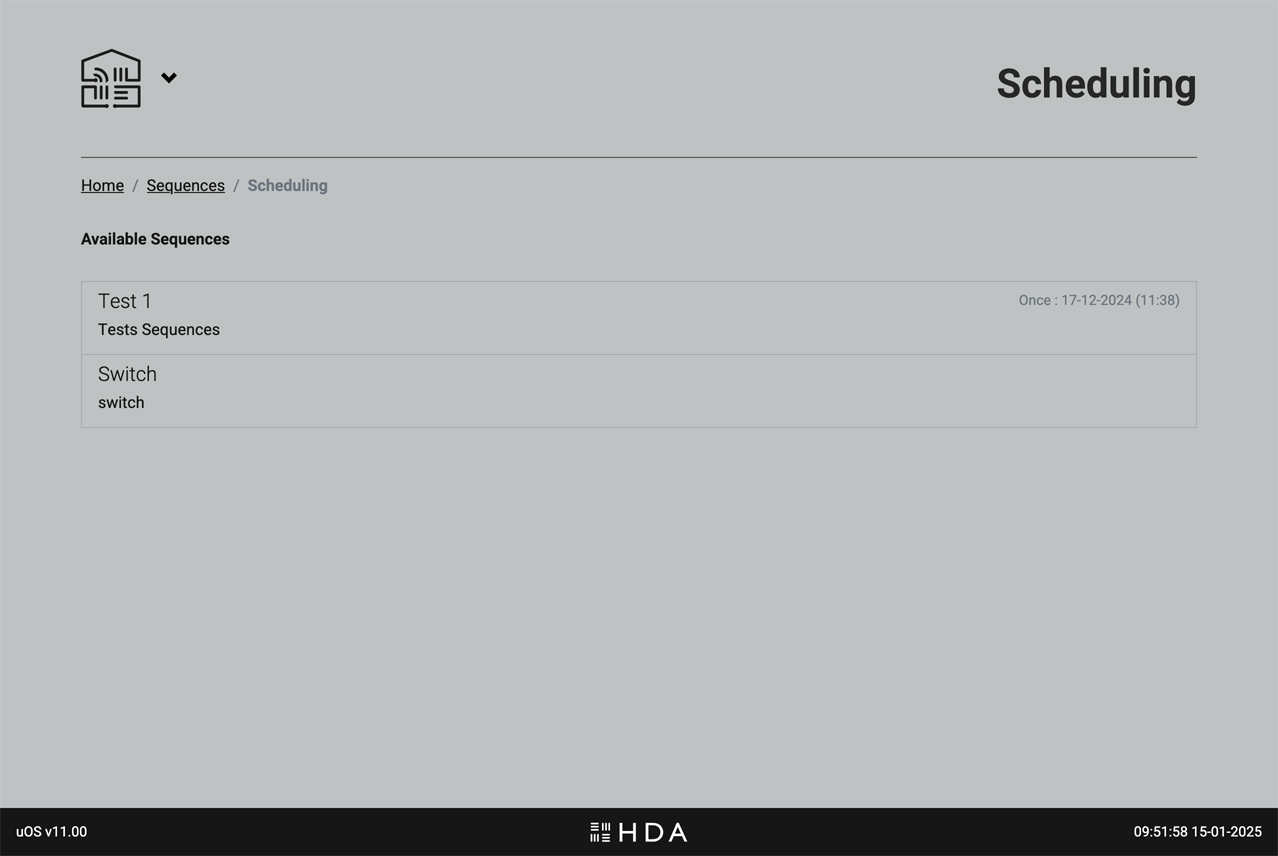
Take any Smart Automation and instruct uOS to execute them automatically for you.
After your Smart Automations have been created you can choose to schedule them to suit your project requirements. For example, you may want all displays in an office environment to turn off at 7pm and for this to happen every Monday to Friday.
tv_remote
Remotes
Configure and customise your uControl Remotes.
ADD YOUR REMOTES LAST:
Once you’ve configured your system Zones, installed all packs, set up Smart Automations, and tested everything in the uControl app — it’s time to add your uControl Remote.
Why wait?
This approach streamlines the Remote setup process. By configuring your system first, the settings are automatically copied to the uControl Remote, making the Remote configuration faster and easier. This ensures that your Remote is ready to use with minimal additional setup.
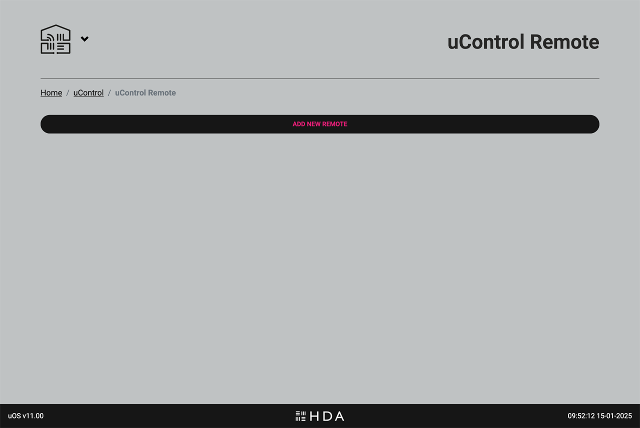
Adding a uControl Remote is a guided process. To add the uControl Remote to your system, ensure that it is on your WiFi network first and is charging before starting.
.
Getting the Remote on WiFi & configuring it for use.
A simple interface for walls and desktop applications.
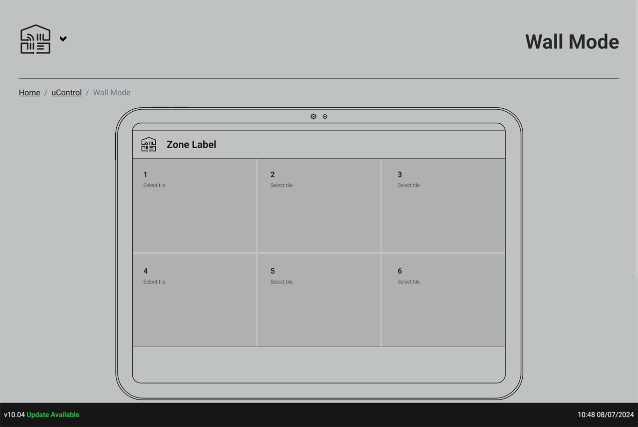
Create a simple 6-tile interface and fix those controls to a single Zone. Perfect if you are going to mount an iPad to a wall or for desktop applications.
.
Design a simplified interface for the uControl app called “Wall Mode.” This mode will display only 6 large tiles on the iPad screen when held in landscape orientation.
Wall Mode is ideal for iPads mounted on walls or placed on tabletops. It makes using the app easier for newcommers or those that do not know how to use the system by hiding all the other menus and options, and presenting the user with just 6 essential controls for a single zone.
IMPORTANT:You can not configure Wall Mode until you have setup Smart Automations. It is recommended that Wall Mode is configured after any uControl Remotes.
To configure a tile, simply click or tap on the tile that you want to configure and add your Smart Automation to it. If uControl driver packs support wall mode configurations then you will have the option to add a driver widget to your tile (e.g Sonos) so that you can see realtime data on that particular tile.
mic
Voice Control
Amazon Alexa voice control
Settings to enable or disable Amazon Alexa voice control if your HDA hardware or configuration supports voice command control.
This section allows you to enable or disable Amazon Alexa voice control for your HDA system.
Compatibility
Please note that voice control functionality depends on your specific HDA hardware and system configuration. If your system supports Alexa integration, you’ll find the following options:
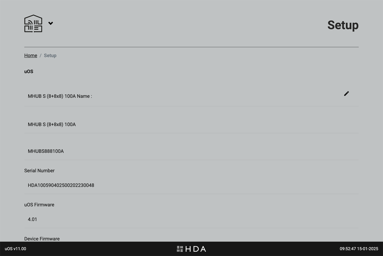
Configure general settings related to your uOS controller. Don’t confuse this with the AV Settings page, which handles hardware-specific configurations.
What you will find on this page
Names and software versions: The official name for your HDA device(s) along with current software and firmware versions.
Timezone: Set the timezone for uOS. By default, uOS will sync its time to GMT clocks. If you intend on using Scheduling to automate your Smart Automations then it is recommended that you set this to your timezone. This is a manual setting.
Access control: Set a PIN code to lock access to uOS. It is STRONGLY RECOMMEDED that you keep a record of this PIN somewhere safe or connect your system to HDA Cloud so HDA Support can recover this for you. Once the PIN is set and in the event that it is forgotten or lost, only a system reset will recover your system.
group
User Accounts
Warranty extension and improved customer service
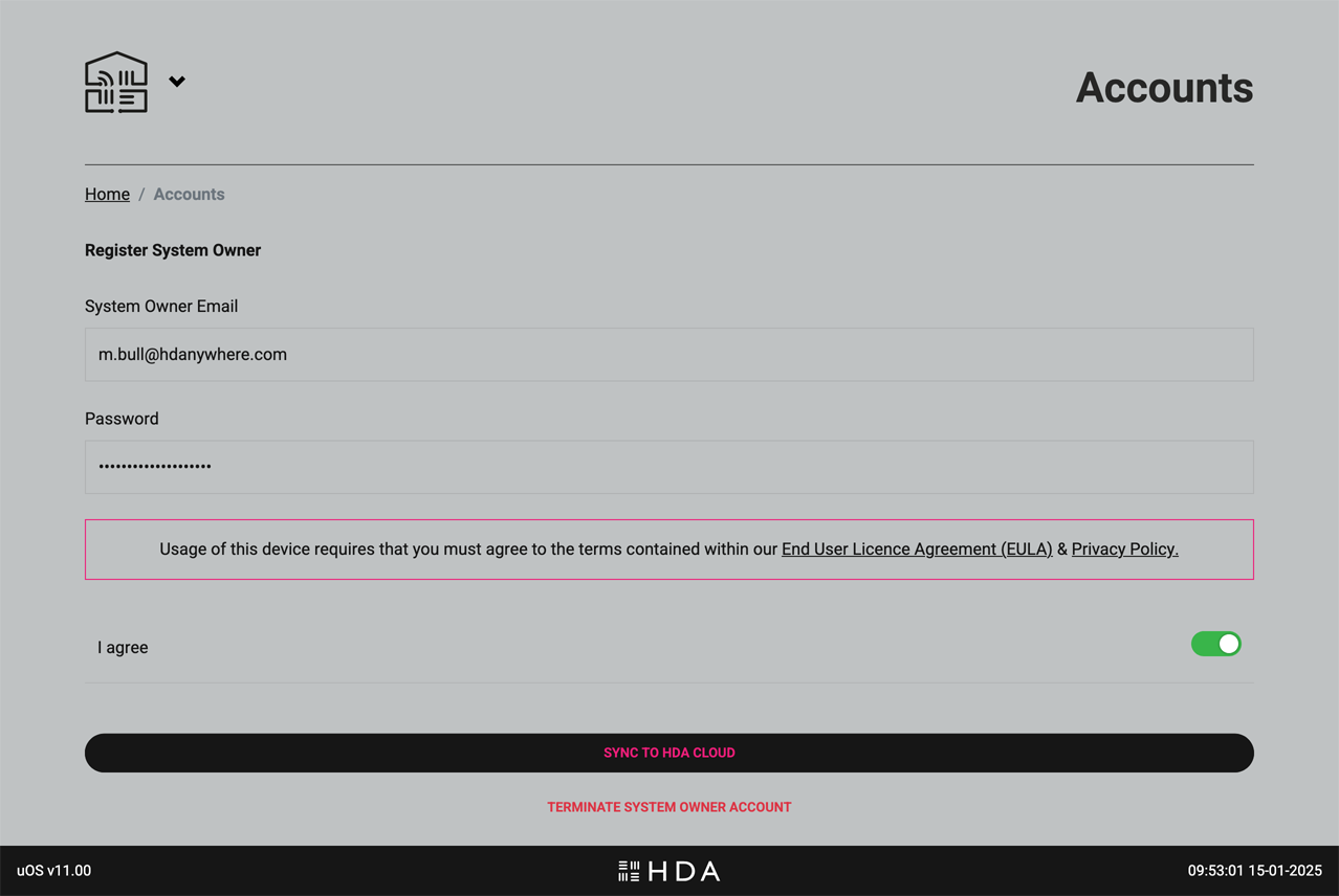
Choose if the system is able to communicate with HDA cloud servers for remote management and advanced customer support.
User Accounts connect your HDA device to HDA Cloud, our global data storage and service delivery platform. There are multiple benefits of connecting your HDA device to our cloud servers but the most common reason is the free warranty extension if this is done within 30 days of purchase.
There are two types of account: 1) Owner/User Accounts which belongs to the owner of the HDA device(s) being registered and 2) HDA Pro Accounts which can be used for monitoring the system remotely.
At all times the Owner Account has executive control of uOS, their HDA Cloud account and their HDA device hardware. It is possible to terminate HDA Pro access directly from this page. The absense of an Owner Account will keep the unit technically offline (with the exception of critical updates) and no information about the system or its state will be sent to HDA servers.
lan
Network
Ethernet and WiFi settings for your HDA device(s)
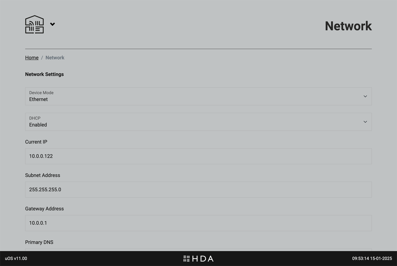
Change network settings for uOS to suit your LAN environment
Adjust uOS’ network settings to suit your Local Area Network configuration. IMPORTANT: proceed with care when changing these settings as you can lose connection to your controller if you make a mistake.
build
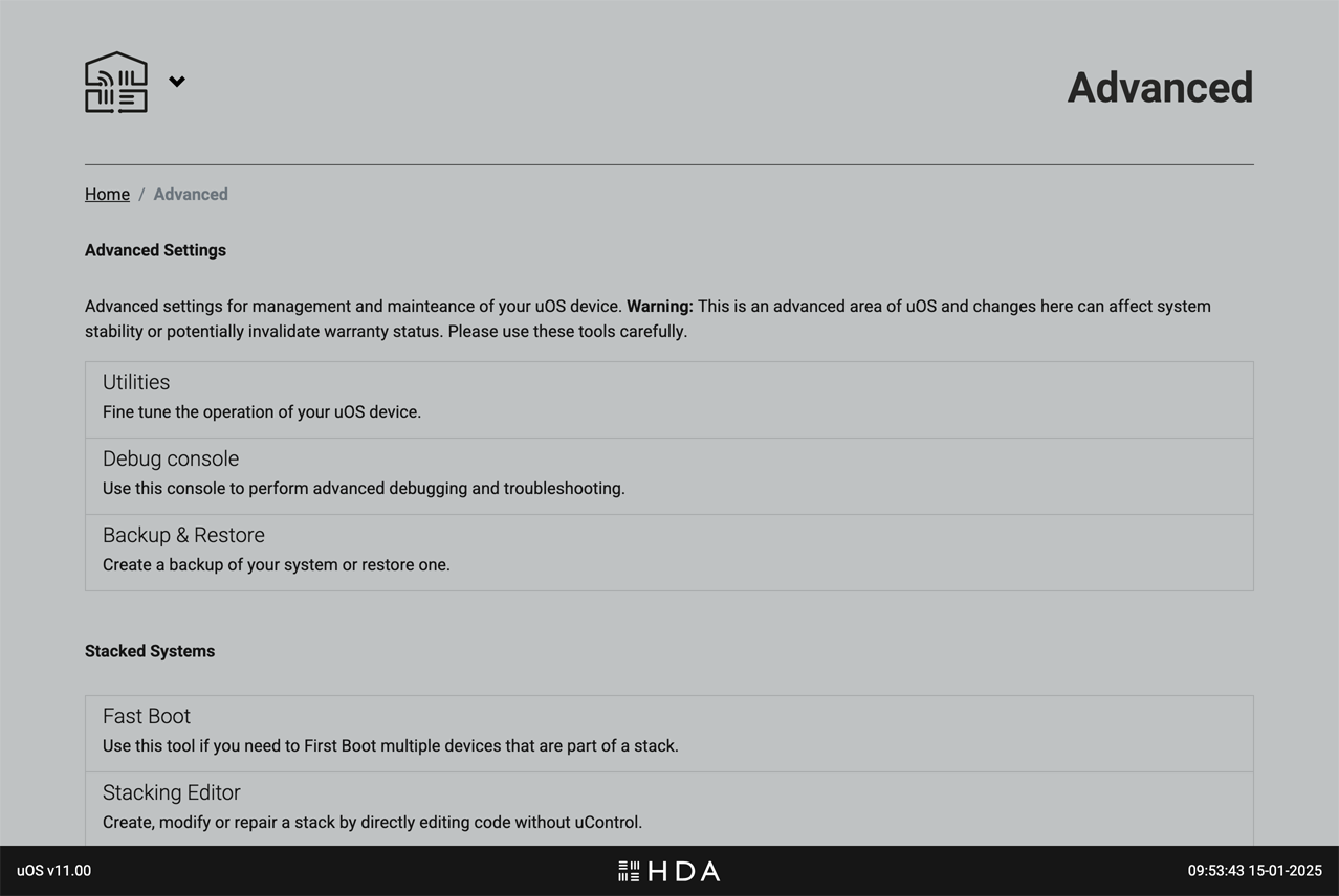
Advanced
Power-user access
Access advanced tools to troubleshoot or speed up deployment of uOS. Use caution accessing the features of this page.
Advanced settings for management and maintenance of uOS. Warning: This is an advanced area of uOS and changes here can affect system stability or potentially invalidate warranty status. Please use these tools carefully.
Before making any changes on this page, ensure you have a thorough understanding of the potential impact. If you are unsure about any settings, please contact HDA support for assistance.
Do you have the correct guide?, please be aware this guide is for legacy systems.
When an MHUB video device is paired with an MHUB AUDIO device we call that a Stack. Stacks can contain up to 4 MHUB products with 1 Master device and 3 slave devices. Master devices can be either VIDEO or AUDIO, slaves are AUDIO only.
Below are a few examples of stacked systems.
Master : MHUBPRO4440, Slaves : 3x MHUBAUDIO64
Master : MHUBAUDIO64, Slaves : 3x MHUBAUDIO64
Master : MHUB4K44PRO, Slaves : 2x MHUBAUDIO64
To create a stacked system you will need to download uControl (available on iOS and Android app stores), and your MHUB hardware will need to be powered on and connected to your network.
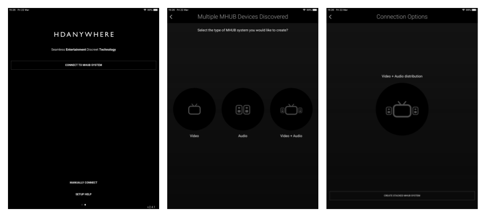
Open the uControl app and select ‘Connect to MHUB System‘. The following screens will be displayed. uControl will search your network for all MHUB devices. To create a stack select ‘Video + Audio‘
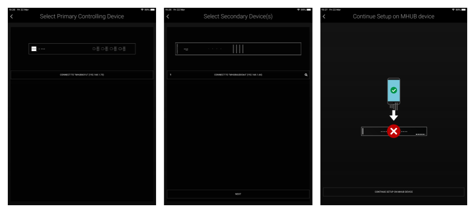
uControl will now ask you to select first a master device, then upto 3 slave devices. (The order in which you select the slave devices will be their order in the stack. this is indicated by a numeric value on the left side of the device button. If you are unsure which MHUB AUDIO device is which you can simply click on the Identify button at the side of each device which will start the HDA and AUDIO logo flashing.)
Once this is done you will be taken to MHUB-OS where the first boot Process will be run.
 Accessing the menu