Asides

  • mHub 2K control system integration

    The mHub 2K range has full support for most popular control systems via serial (RS232) or IP.

    All control strings and current available drivers are available in the mHub control pack, available here – mHub Control Pack

    To control the mHub 2k unit via IP you will first need to discover it by using the mHub controller software available in the control pack.

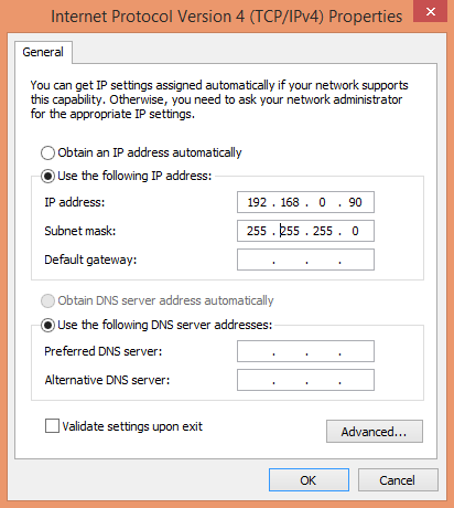
    The mhub 2K’s IP address is pre-configured as 192.168.0.100, your computer will need to have it’s IPV4 range configured to be within the same range initially while you setup the matrix. To configure your IPV4 settings you will need to navigate to the following menu

    ->Network and sharing center
    —>Ethernet
    —–>Properties
    ——->Internet Protocol Version 4 (TCP/IPv4)
    ———>Properties
    IPV4

    Configure your settings as shown in the image, this will change your computer IP range and you will temporarily lose internet connectivity (if your previous IP range was different from this)

    Once you have changed the IP settings on your PC, open the Mhub controller software
    mhub controller pic 1

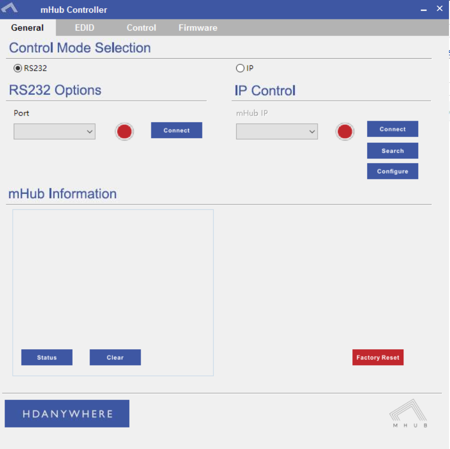
    In the mHub controller software select IP and then press the ‘search’ button, this should locate your mHub matrix. Press ‘connect’ the red button should turn green.

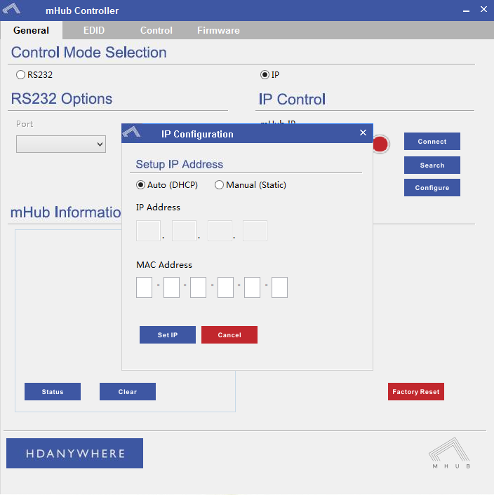
    Press the configure button
    mHub IP

    Change the IP configuration to manual (static), and then enter an IP address within your home network range that is not currently being used and then click ‘Set IP’.

    You can now go back into your IPV4 settings and set them back as they were before (obtain an IP address automatically)

    Your matrix is now on your home network and will be able to receive IP commands from whatever control system you are using.

    Looking for the mHub 4K information, go here – mHub 4K
  • MHUB-OS 8: a quick guide to zones

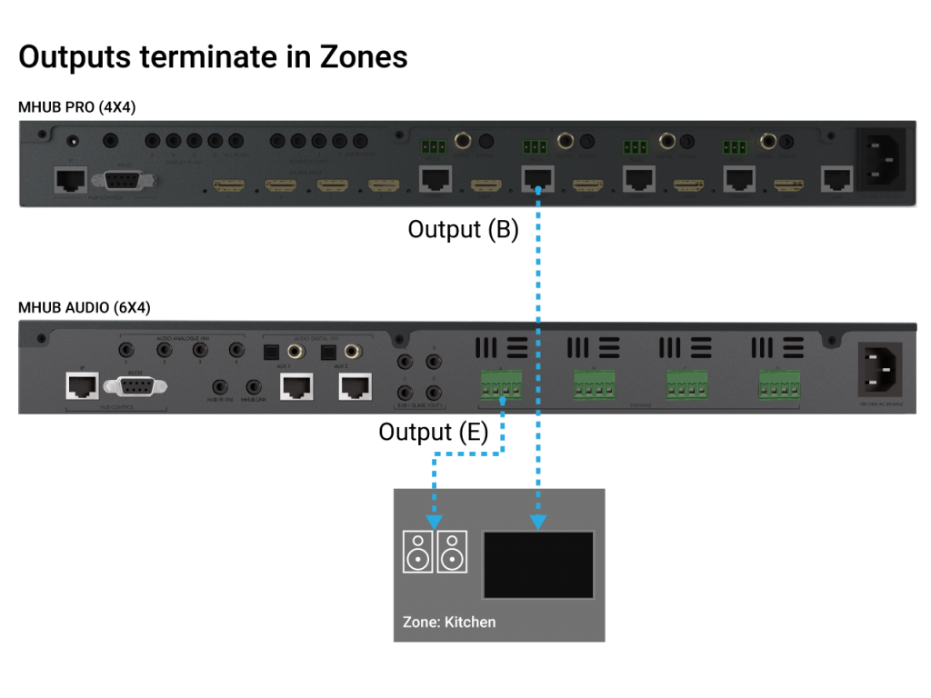
    Zones define a physical space in a property where outputs from MHUB terminate.

    A Zone can include a maximum of 1 video output and a maximum of 4 audio outputs. For example, you can create a zone called “Kitchen” and assign 1 video and 1 audio output to it to provide you with viewable TV and sound. A Zone must contain at least 1 output from an MHUB for it to be addressable for control. Note: outputs can not be shared or split to more than 1 Zone.


    MHUB zones

  • How to deal with Picture loss/dropout on your display(s) when using MHUB

    ​Your MHUB is similar to a central heating system in that there are many components that all need to come together to deliver a working system. An intermittent or full loss in picture on one or more displays can be down to a number of things.

    • HDMI cables going into MHUB and from the display receivers to the displays
    • Your network cabling infrastructure, the termination quality, the distance of the cable run and the number of times that cable runs through patch panels or wall plates.
    • The physical output port on the MHUB
    • The display receivers
    • The actual source devices (more common than you think!) and the AV they are outputting (4K, 1080p, surround sound, HDCP format etc)

    Unfortunately, there is no fast way to determine this. To do this test correctly you will need to test for several days to ensure the results are accurate and your system is stable.

    If dropout occurs on one display in your property…

    The first thing to do is disconnect all sources and outputs from MHUB so you are left with 1 source (preferably the source you notice picture loss on) and 1 output (preferably the display you notice picture loss most frequently on).

    Grab a piece of paper and log the following outcomes when you test the following:

    1. If picture loss is happening only in one location in your property then take a display receiver (and the HDMI cable going into the display) from a known working location and swap it in the area you’re noticing picture loss.
    2. If you still experience picture loss then run freshly terminated Cat 6 cable from the MHUB to the display receiver point-to-point (no breaks in cable) and check again.
    3. If you are still having a problem then connect your new Cat 6 cable to another output port on MHUB.
    4. If #3 doesn’t resolve the problem then disconnect your source from MHUB (and the HDMI cable) and plug it directly into your test display using the same HDMI cable.
    5. If the picture is stable then take the source and the HDMI cable back to MHUB and plug it into another HDMI input and test for picture loss on your display.
    6. Finally, drop the resolution on your HDMI source to something you know the display will accept easily (something like 1080p Stereo)

    If dropout occurs on all displays in your property…

    Start by disconnecting your source from MHUB (and the HDMI cable) and plug it directly into a test display using the same HDMI cable.

    Grab a piece of paper and log the following outcomes when you test the following:

    1. If the picture is stable then take the source and the HDMI cable back to MHUB and plug it into another HDMI input and test for picture loss on your display.
    2. If you still experience loss in picture then drop the resolution on your HDMI source to something you know the displays will accept easily (something like 1080p Stereo)
    3. Remove all outputs from MHUB until you’re left with only one output connected, it could be any port but we recommend starting with A. Check for a stable picture and repeat for each output port individually.
    4. If all ports passed the test in #4 then start connecting additional outputs back to MHUB starting B (so you should have A + B now), if the picture is stable add output C and so on.

    If you log any problems or positives with each test then let us know and we can assist you further.

  • Controlling Gen 1 Shelly devices from uOS

    This guide explains how to pull data from Shelly’s API so you can control it directly from uOS.

    Shelly in uOS

    Please note: this guide covers how to execute a command for a Shelly light, if you are using a different device the same logic applies, you only need to change the parameters. Please find the link to Shelly’s API document below for commands relating to different devices.

    What this guide will cover:

    1. How to control Shelly lighting in your home.
    2. How to add that API into uOS.

    Important: you must have the IP addresses first

    There are a few ways you can get the IP address if your Shelly device:

    1. Use a network scanner app like Fing to find Shelly on your network.
    2. Log into your wireless router and look for Shelly in the DHCP table.

    What a typical Shelly command looks like

    /color/0?turn=on&red=0&blue=0&green=255

    This only shows the logic of a Shelly command, you may be controlling a relay and therefore need to use different parameters. There will be a link at the bottom which will take you to Shelly’s API documentation where you can find all their codes.

    /color/0?
    This is the mode of the device and declares it is an RGBW2 controller. If you were writing a command for an automated blind it would be /relay/0?.

    turn=on
    This affects the state of the device.

    red=0&blue=0&green=255

    Testing your APIs

    You can test your Shelly command in the URL to see if it works. Make sure to include http:// for it to work properly.

    If it doesn’t work then try the following:

    • Make sure the IP address is correct.
    • Make sure that you do not have any typos.
    • Ensure that your IDs are correct and that you’re observing a light in the correct room and location.
    • Make sure that the structure of the API matches our example no spaces, no special characters, data is in the correct case (often lowercase).

    How to add your APIs into uControl

    Need more help with the API? Get in touch.

    All HDA staff are able to help with any API questions you might have including any advanced features. Get in touch for help or assistance.

  • MHUB PRO 2.0 and MZMA Stack

    mhub-pro2-hero-guide

    Please read:

    This guide will show you how to build a stacked system using an MHUB PRO 2.0 and an MZMA (6×4) 55 with uControl acting as the main method of control for the system.

    Make sure the only HDA devices on the network are the ones you want to put into the Stacked System. If you still cannot discover them in the app consider your network infrastructure, the app may struggle to find the system(s) if there are things like network switches in the residence, so try simplifying it whilst going through setup.

    This guide is intermediate in difficulty and assumes that you have installed MHUB before in standalone mode.

    It is strongly recommended that you read this guide carefully before commissioning your stacked system to ensure all features of the system work as expected.

    25 minutes (approximately) to work through.

    What you will learn:

    Checklist

    To create a stacked system please make sure you have the following before you start:

    • MHUB PRO 2.0 (4×4) or (8×8)
    • MZMA (6×4) 55
    • Zone Processor, uControl Connect (x1)
    • Audio cable(s) to create connections between your MHUB PRO 2.0 and MZMA (6×4) 55

    CHECK SOFTWARE VERSIONS:
    Check that ALL hardware above has been updated to the latest software version BEFORE you start configuration on uControl app.


    Glossary

    the following terms are used throughout this guide.

    Foundation Layer

    Foundation Layer

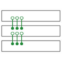
    The MHUB system which is directly connected to a video source(s) is referred to as the Foundation Layer. Ideally, this system should be physically installed at the bottom of your MHUB stack. Inside uOS this system is referred to as S1 (see Stack Layer below).

    Connections

    Connections

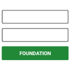
    A Connection is used to define the cabled connections between each component in an MHUB/MZMA Stack. The combination of HDA devices in your Stack will determine which ports can be paired or not.

    Stack Layer

    Stack Layer

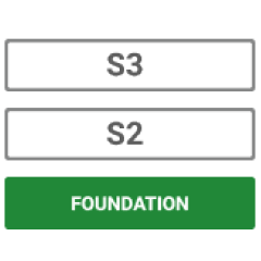
    The Stack Layer is an alphanumeric identifier within uOS, starting from the Foundation Layer (Layer S1). This identifier represents the order of HDA systems that are connected to one another by a Connection. For example, if you had four HDA systems stacked together, then you would start with the Foundation Layer (Layer S1), then the second HDA device (Layer S2), followed by the third HDA device (Layer S3) and, finally, the fourth HDA device (Layer S4).

    Master / Controller

    Master / Controller

    An HDA device (like a Zone Processor) designed to control MHUB and/or MZMA (6×4) 55 systems operating in Stack mode. Any Stack that needs to be controlled by uControl must have a Master / Controller present in your setup. This is identified as M1 in uOS.

    uControl

    uControl

    uControl is our control system for configuration and control of stacked systems. When we refer to “uControl” in this article we are referring to our app specifically.


    Wiring

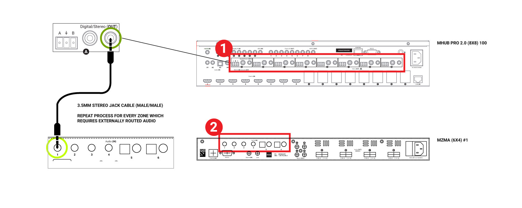
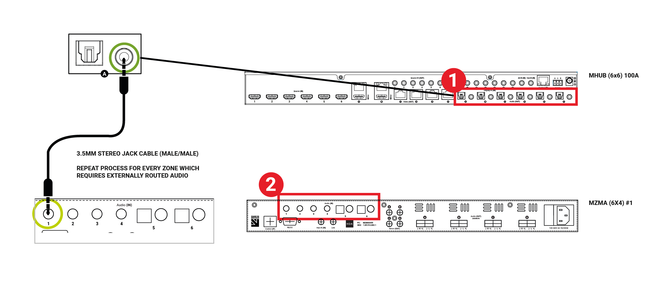
    A video and audio system is made possible by the audio ports on the back of the MHUB PRO 2.0 and MZMA (6×4) 55. Connect the 3.5mm Stereo port labelled Audio (In) on the back of the MZMA (6×4) 55 to the 3.5mm Stereo port on the back of the MHUB PRO 2.0 labelled Audio (Out).

    1. “Audio (Out)”
      The audio ports on the back of the MHUB PRO 2.0 are labelled Audio (Out).
    2. “Audio (In)”
      The audio ports on the back of the MZMA (6×4) 55 are labelled Audio (In).
    Ports used in stack
    Figure 1: Showing stereo connection between MHUB PRO 2.0 and MZMA (6×4) 55.
    1. Connect your 3.5mm stereo cables to the Audio (In) port of the MZMA (6×4) 55 and repeat for every zone.
    2. Connect your 3.5mm stereo cables to the Audio (Out) port of the MHUB PRO 2.0 and repeat for every zone.
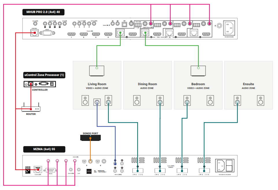
    3. Connect speakers via phoenix connector into the Audio (OUT) of the MZMA (6×4) 55 and repeat for every zone.
    4. Connect your HDBaseT/network cabling into the Video (OUT) of your MHUB PRO 2.0 then into your display receiver and repeat for each zone.
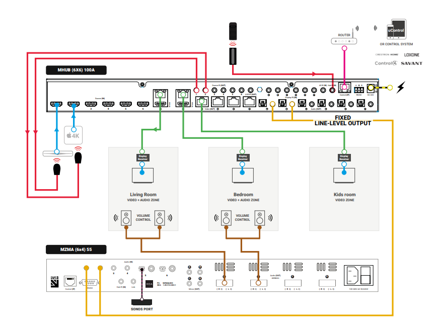
    fig2
    Figure 2: Wiring guide showing video and audio connection between MHUB PRO 2.0 and MZMA (6×4) 55(s).

    Watch video: How to wire MHUB PRO 2.0 and MZMA (6×4) 55 stack

    This video describes how to wire an MHUB PRO 2.0 with an MZMA (6×4) 55 to create a stack.


    Initialising your Stacked Video and Audio System using uControl

    Ensure that your MHUB PRO 2.0 and MZMA (6×4) 55 are correctly wired for stacking covered in the part above and that the following is completed:

    • Both MHUB PRO 2.0 and MZMA (6×4) 55 systems in your stack are powered ON.
    • Your Master / Controller device (Zone Processor or uControl Connect) is powered ON.
    • All HDA systems and the Master Controller are connected to the LAN and reachable by their IP address.
    • IMPORTANT: All hardware has been individually updated to the latest software version.

    Configuring MHUB PRO 2.0 and MZMA (6×4) 55 to operate in stacked mode cannot be undone without resetting the system and starting again. Ensure that you have your wiring information handy and that you know exactly how the system is connected together before initialising your stack.

    1. Connect to system

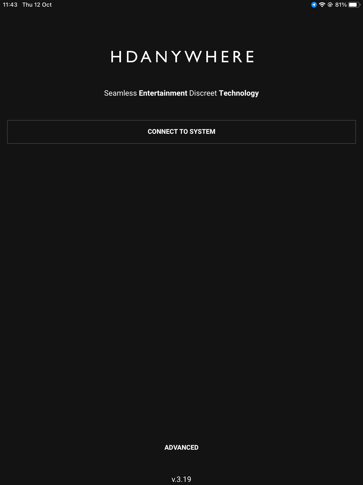
    To get started press connect to system on the uControl Homepage.

    2. Stack

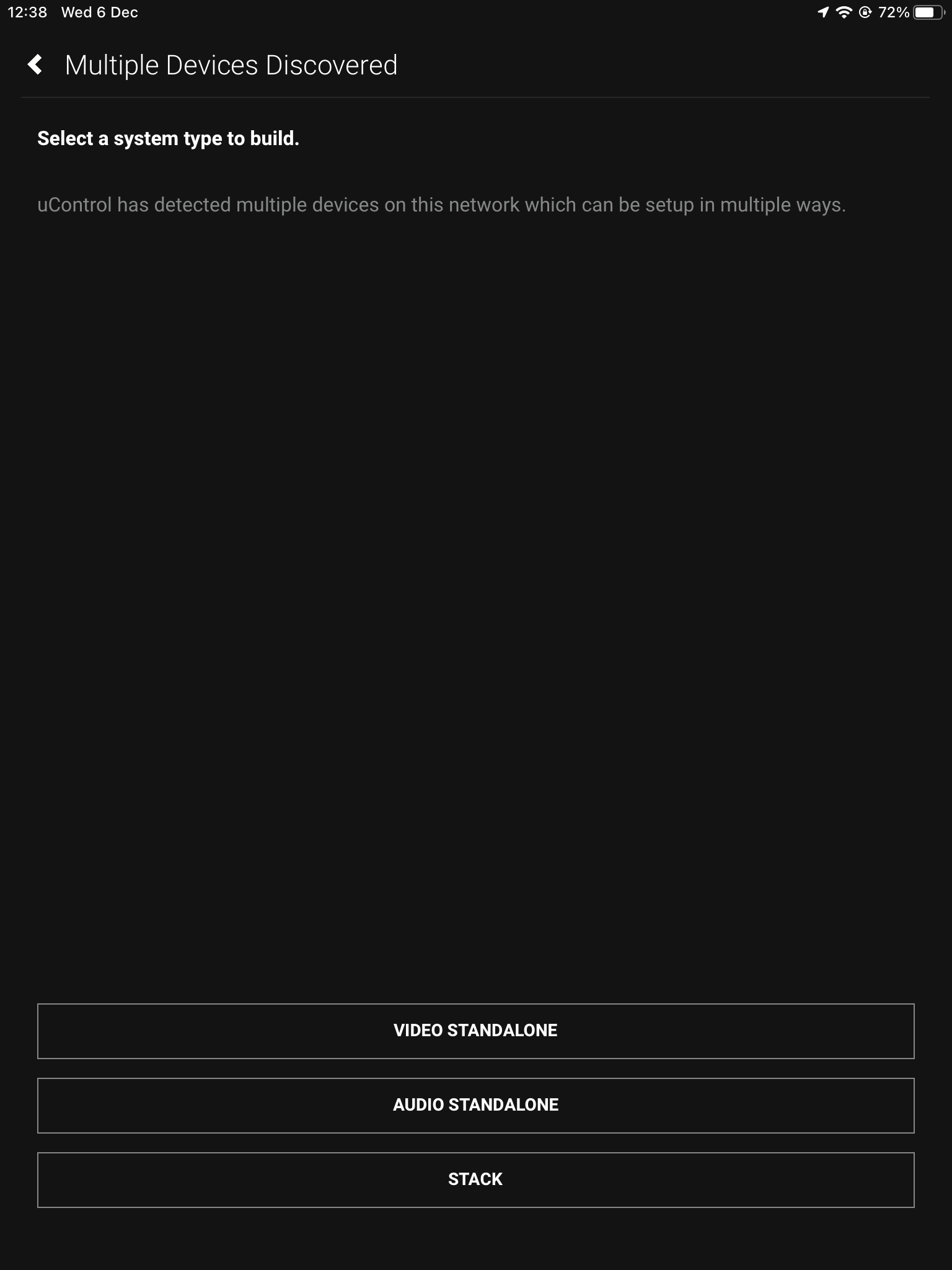
    If the HDA devices are on the network you will be presented with the option to create a STACK, VIDEO STANDALONE or AUDIO STANDALONE, choose STACK.

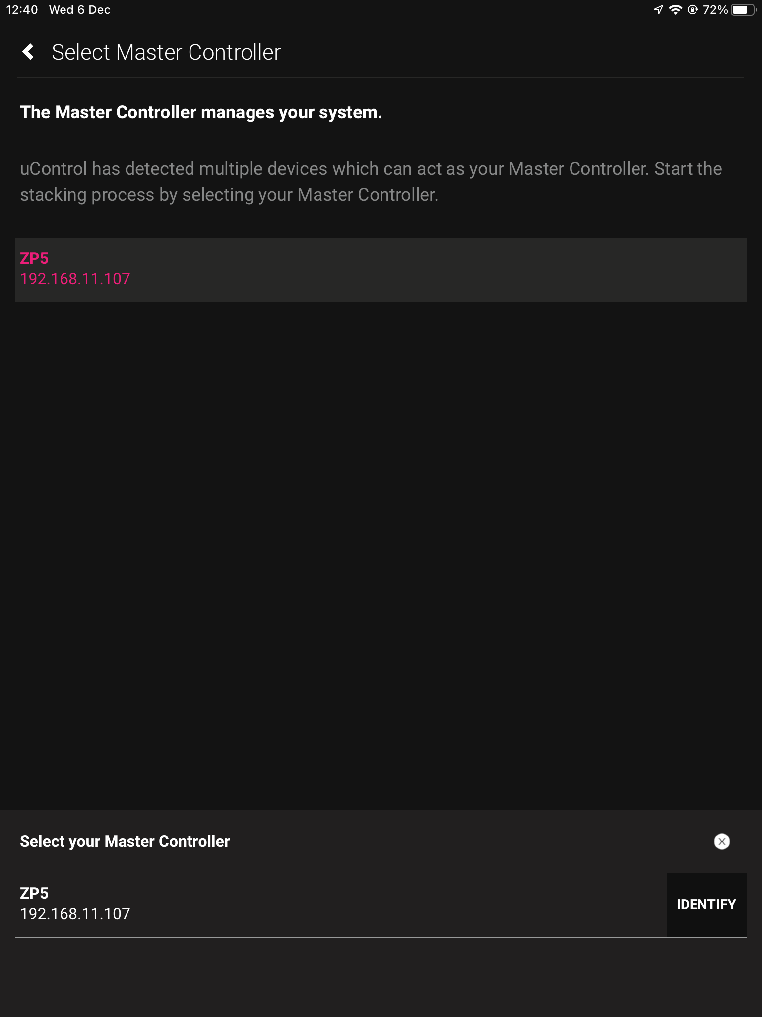
    3. Master Controller

    The Zone Processor acts as the bridge between 2 or more HDA devices and all data goes through this device, acting as a brain. It needs to be selected as the Master Controller.

    4. Setting Stack Layers

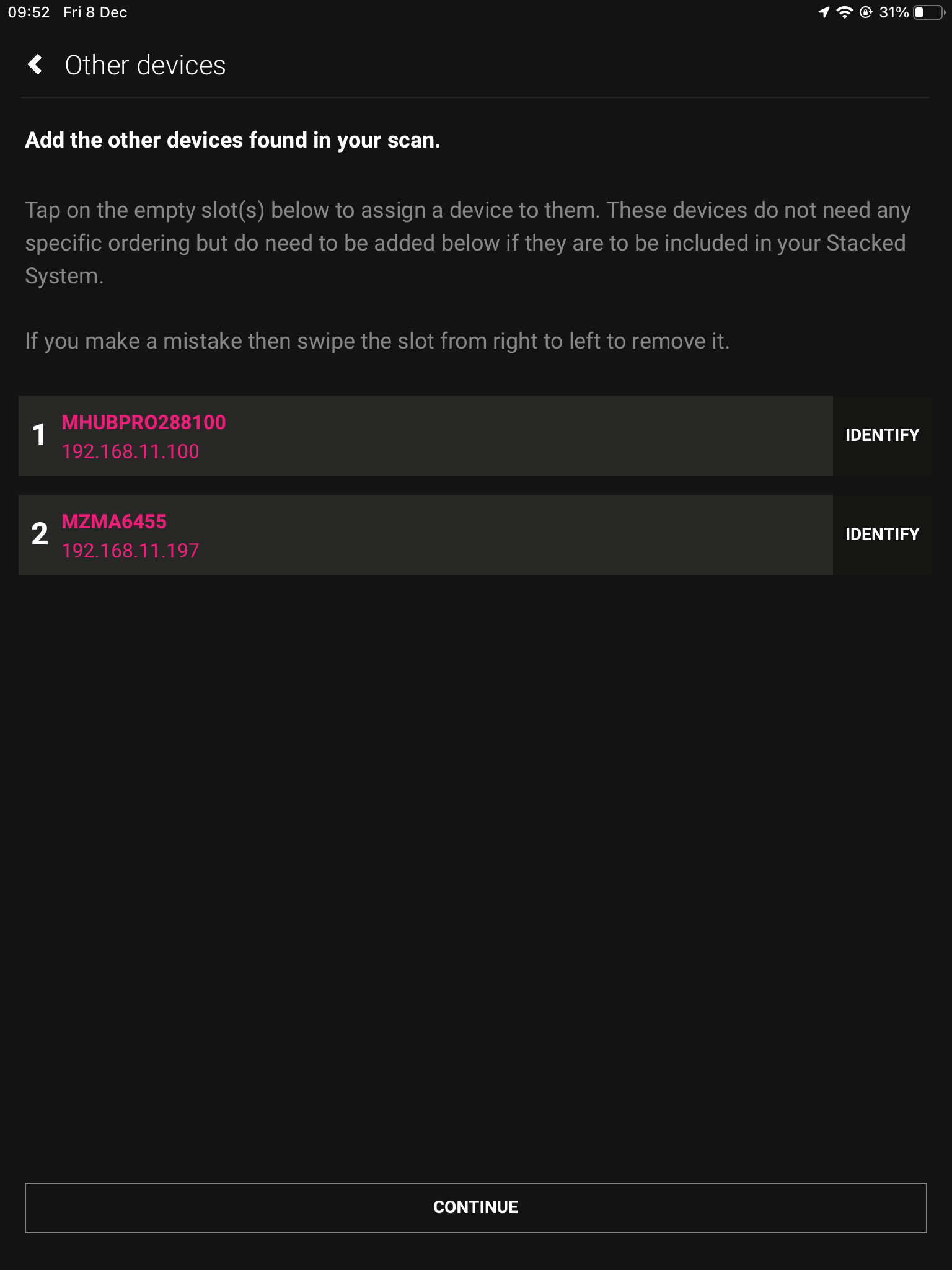
    Select your MHUB as the primary device, and then select MZMA as the secondary device.

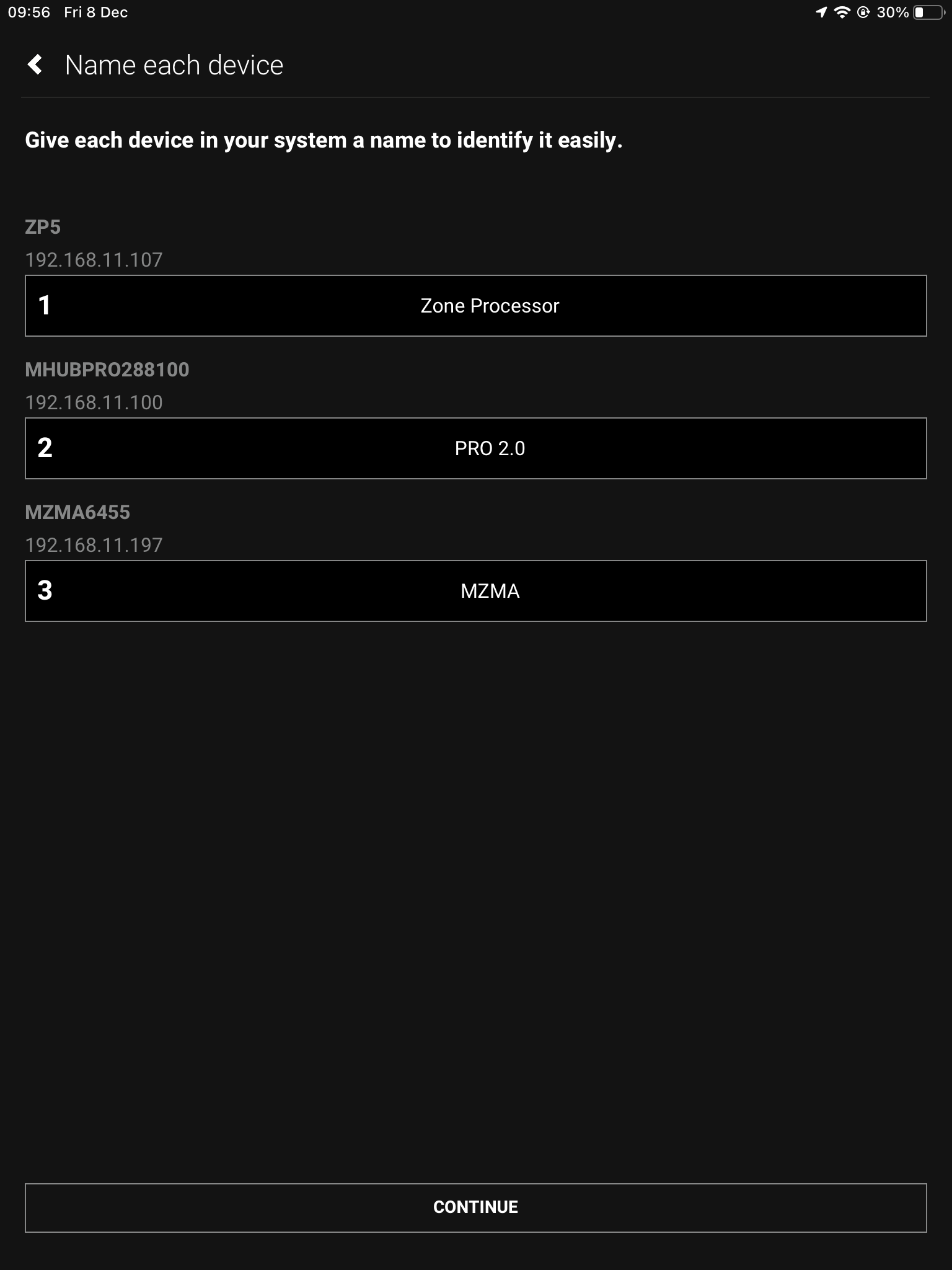
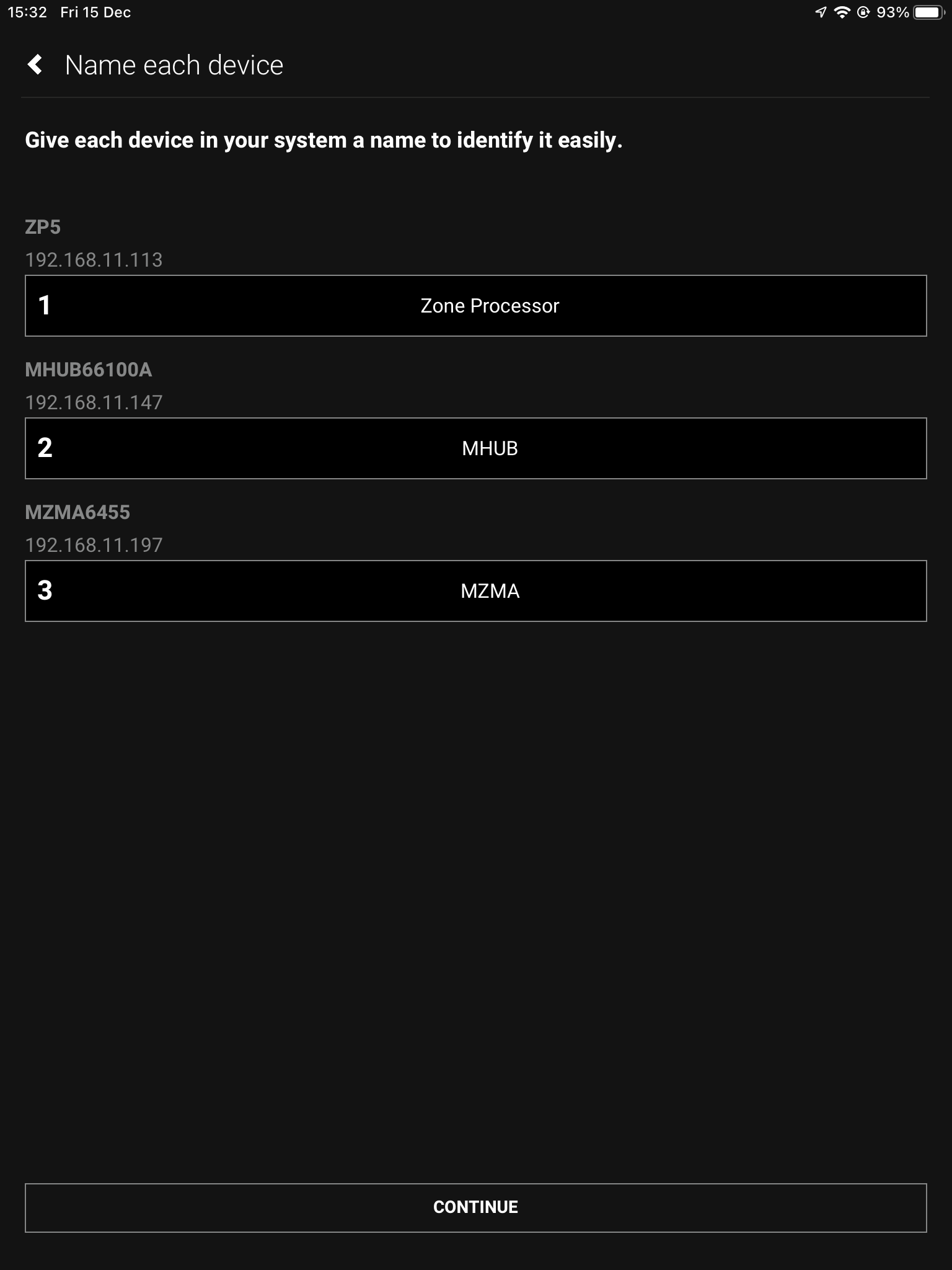
    5. Naming devices

    Name the devices so that they’re easily identifiable.

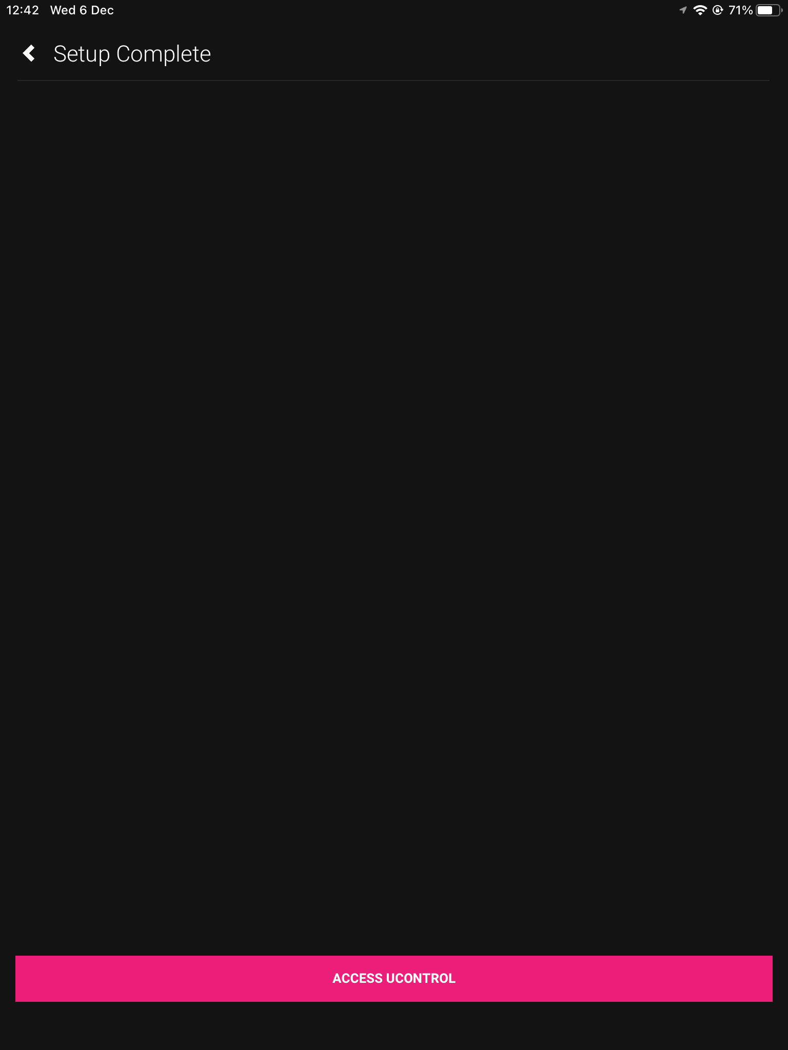
    6. Access uControl

    Your HDA devices are now in Stack mode and are ready for configuration. You can now proceed to perform First Boot of your Stack with the Master Controller (M1)

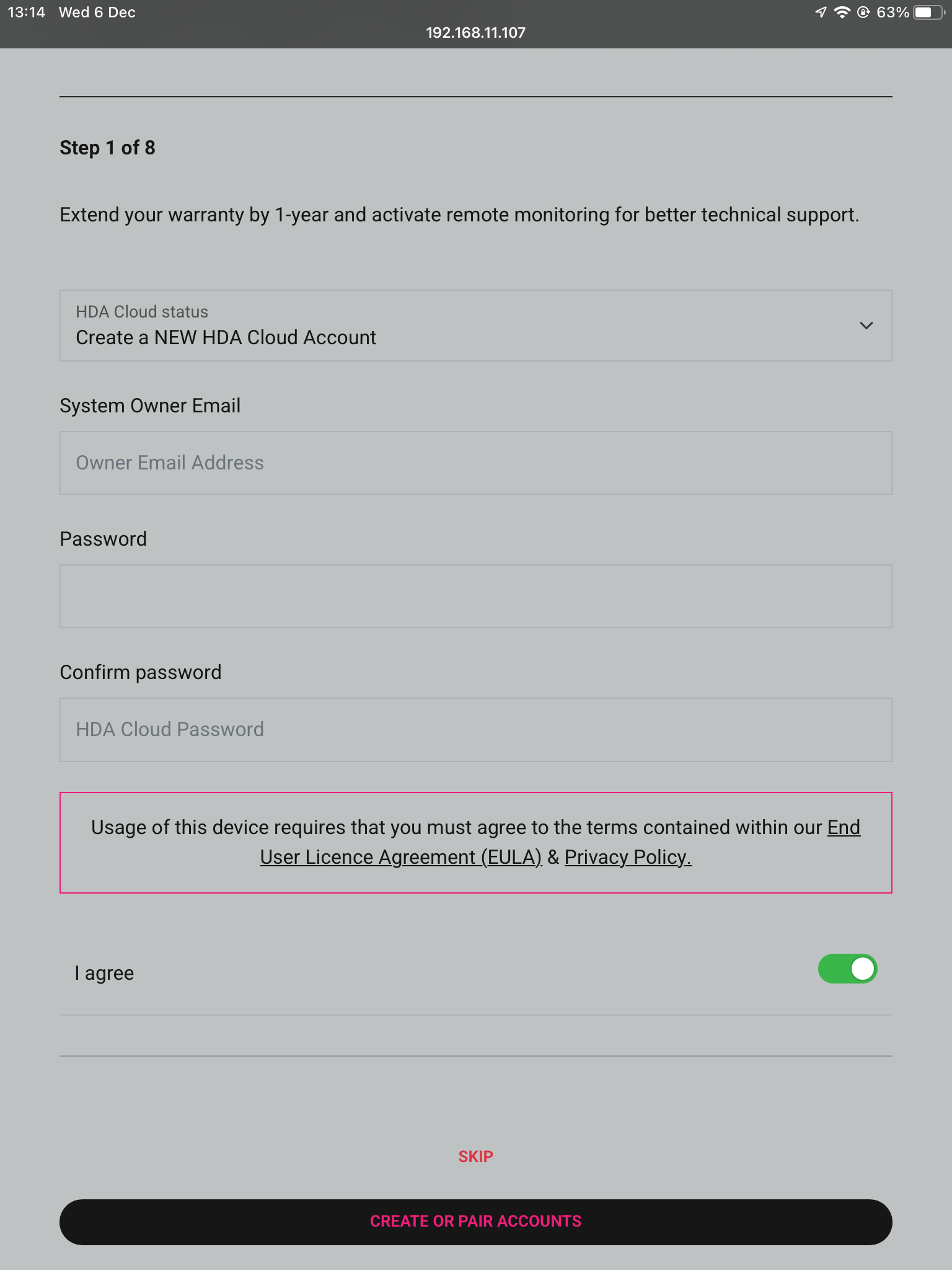
    7. Owner Account

    Owner Accounts allow installers to add their HDA PRO account to their system for additional features, and to increase the warranty period. We recommend you do not skip this step.

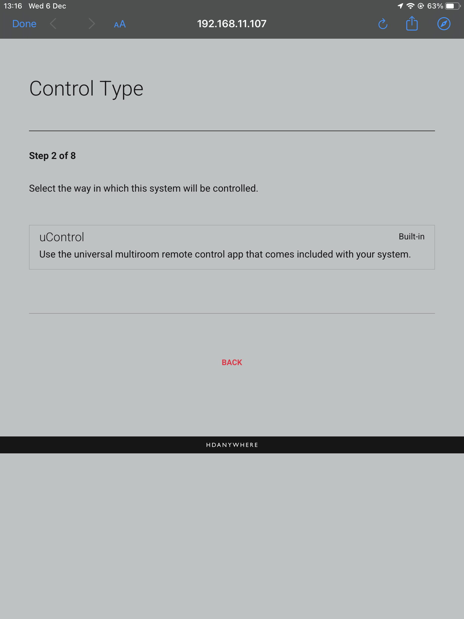
    8. Control Type

    Choose uControl as the Control Type.

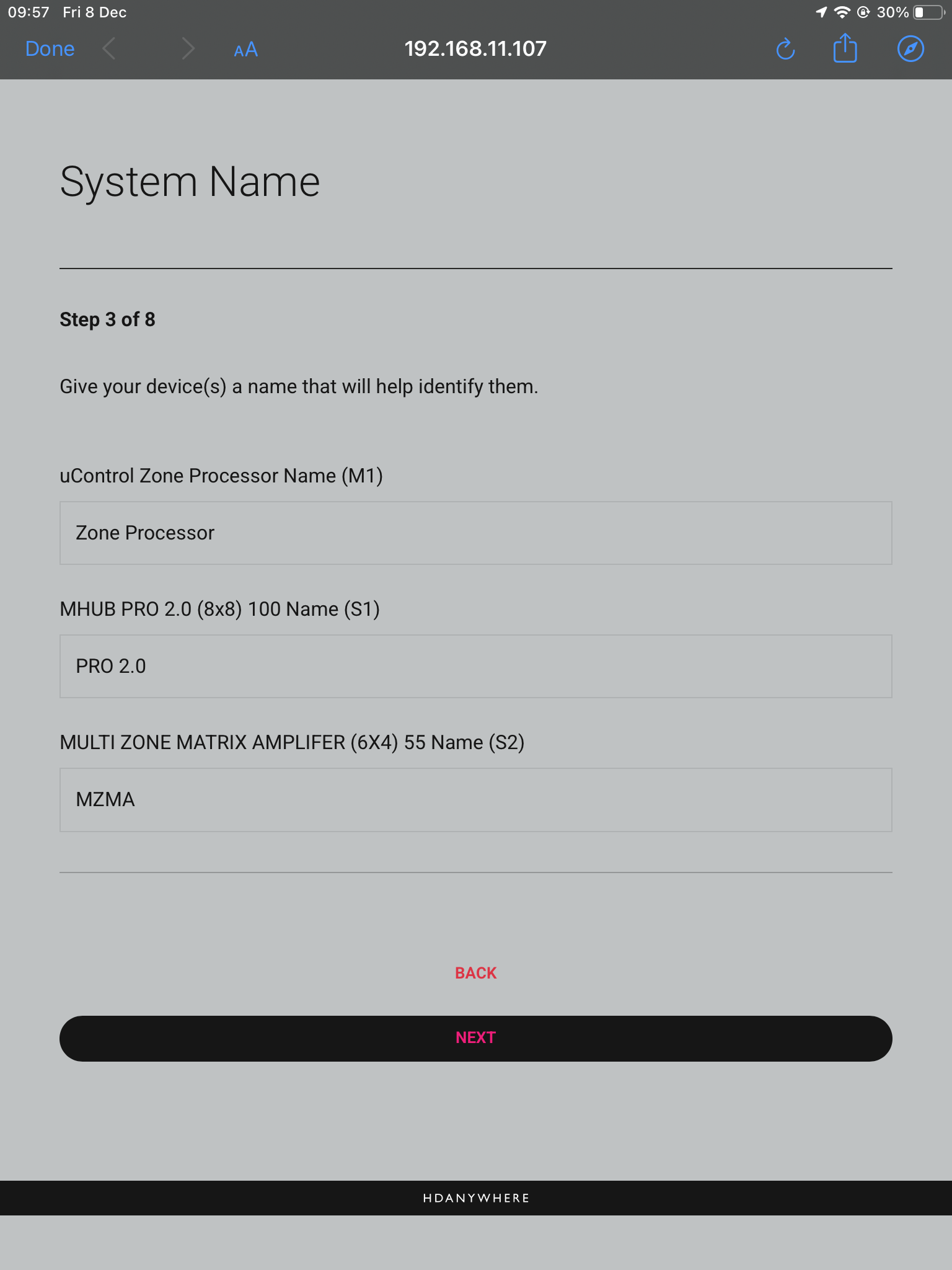
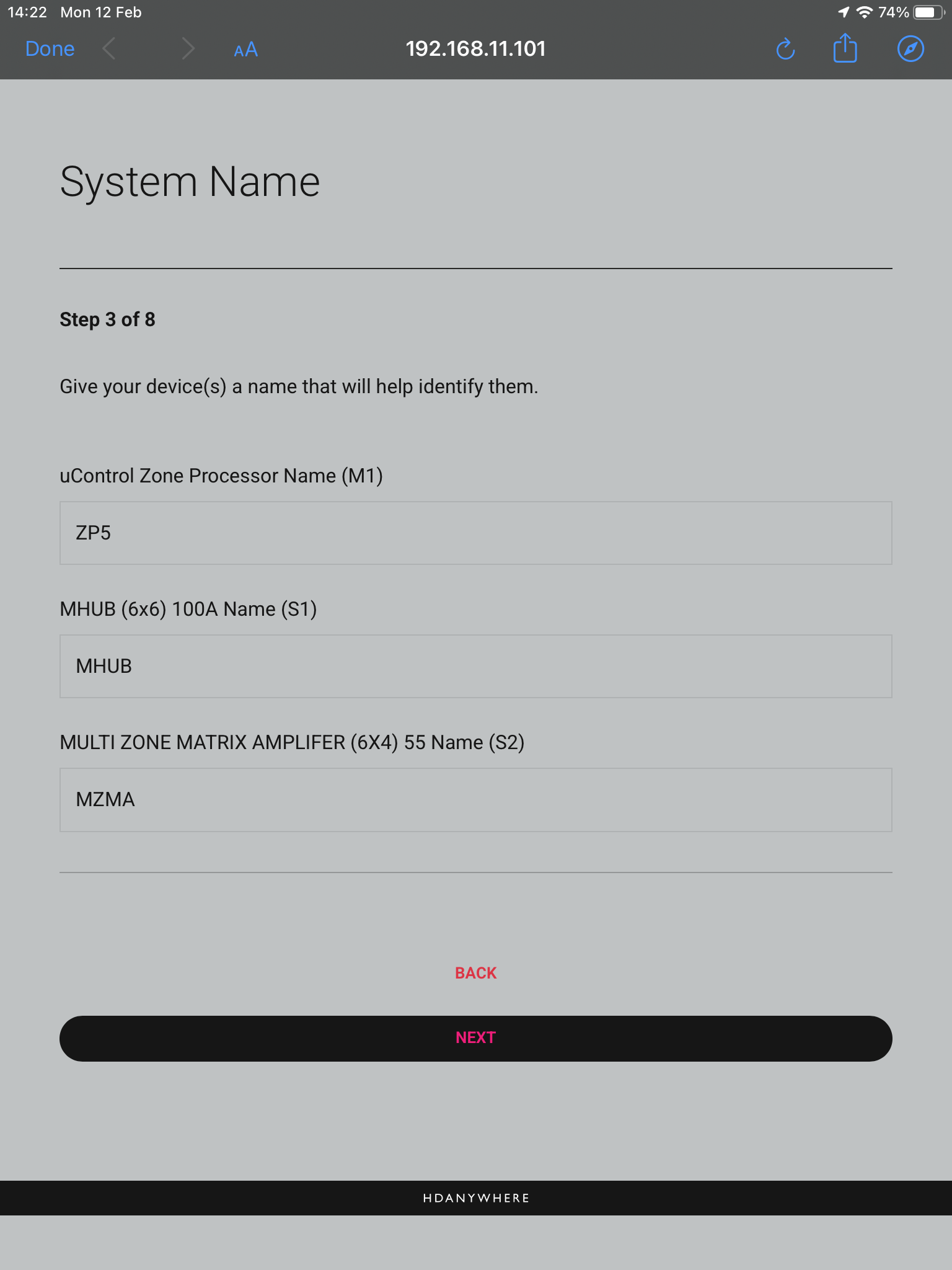
    9. System Name

    Confirm the names of your devices.

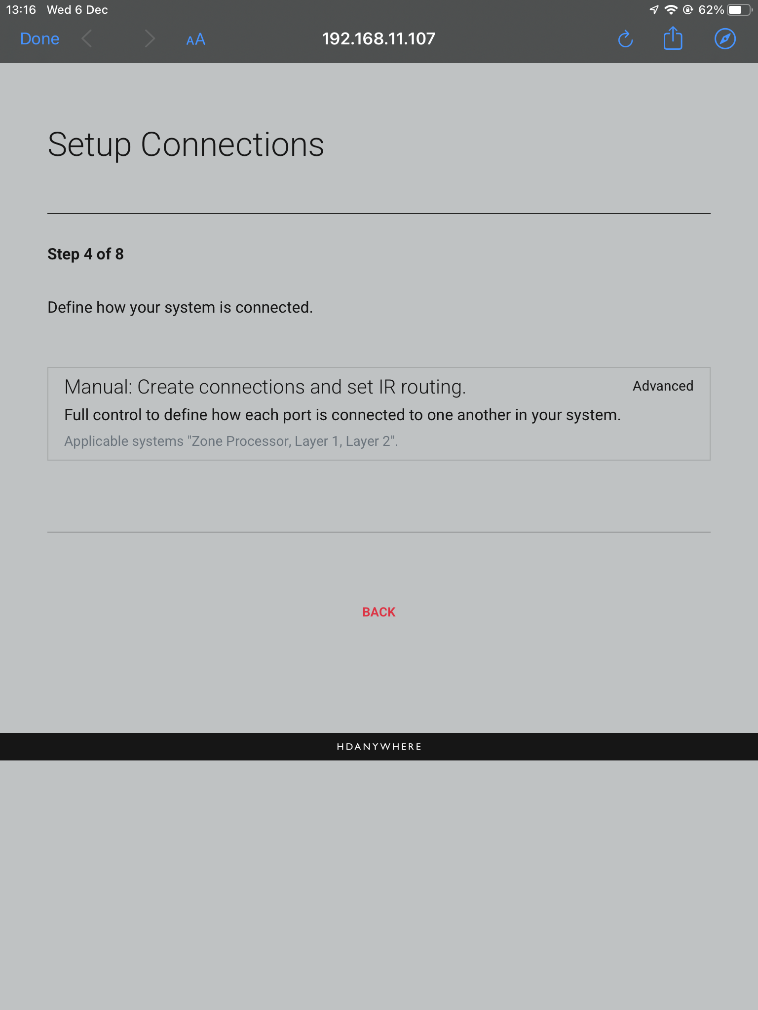
    10. Setup Connections

    This next step will allow us to make the manual connections between the multiple devices.

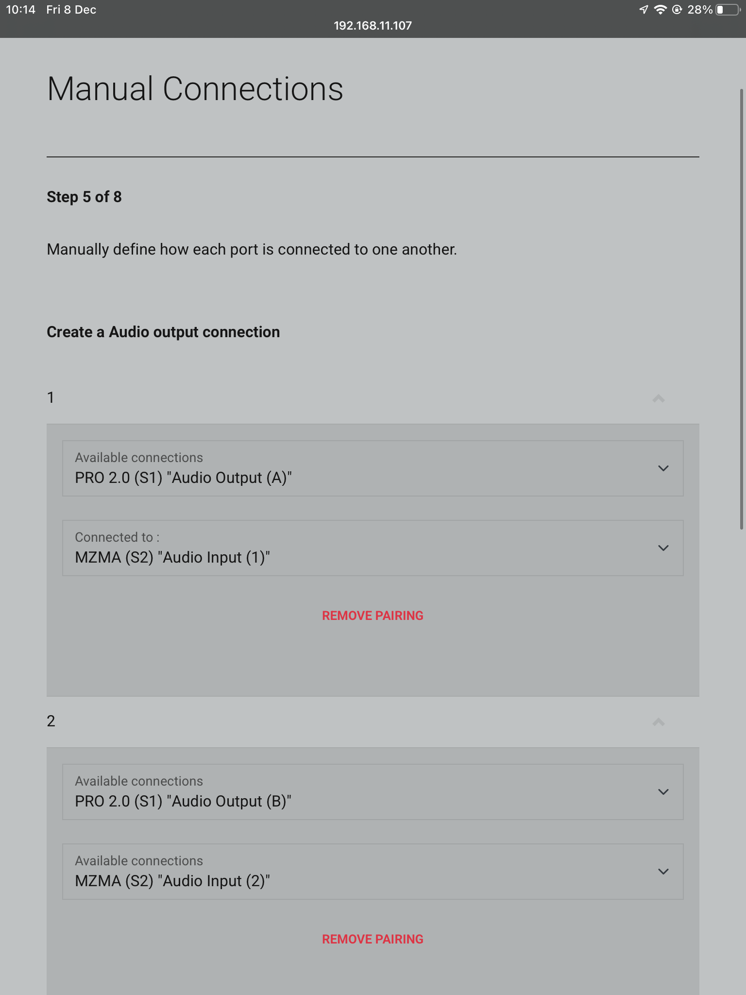
    11. Manual Connections

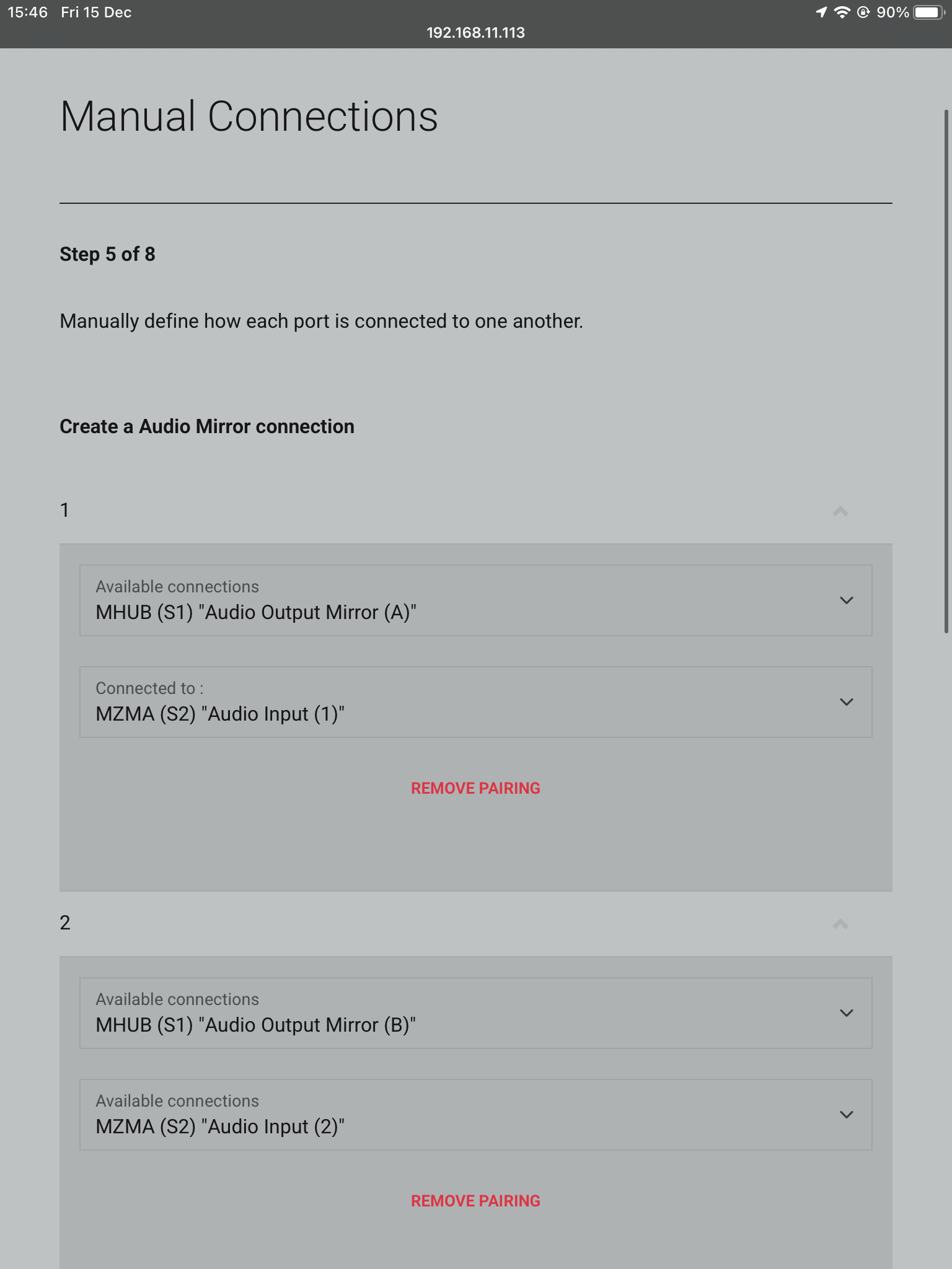
    Connect your ports by linking Audio Input (1) to Audio Output (A), and the same for Audio Input (2) and Audio Output (B). Continue to do so until all your Audio Inputs are linked with your Audio Outputs. If you have 5 or more zones of audio requiring multiple MZMA’s, select MZMA (S3) from the drop down which will be your third HDA device in the stack as the MHUB PRO 2.0 is the primary, or (S1). Repeat the first steps until all Audio Inputs are assigned to Audio Outputs.

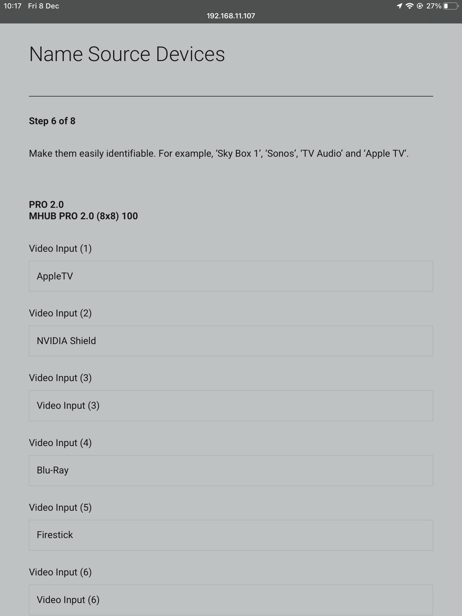
    12. Naming Sources

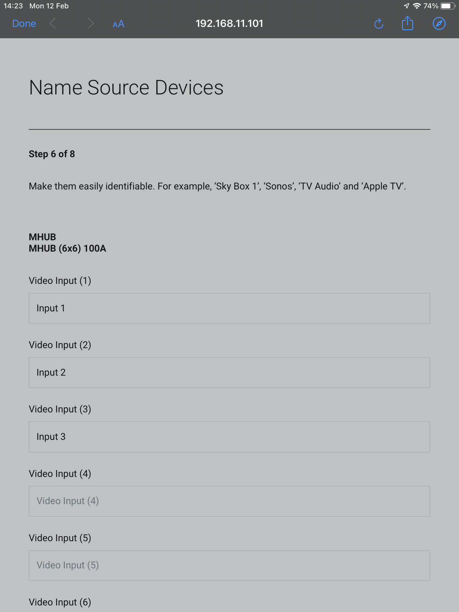
    Name your inputs after what identifies them the easiest. This can be naming it after the specific source that is connected, or naming them incrementally.

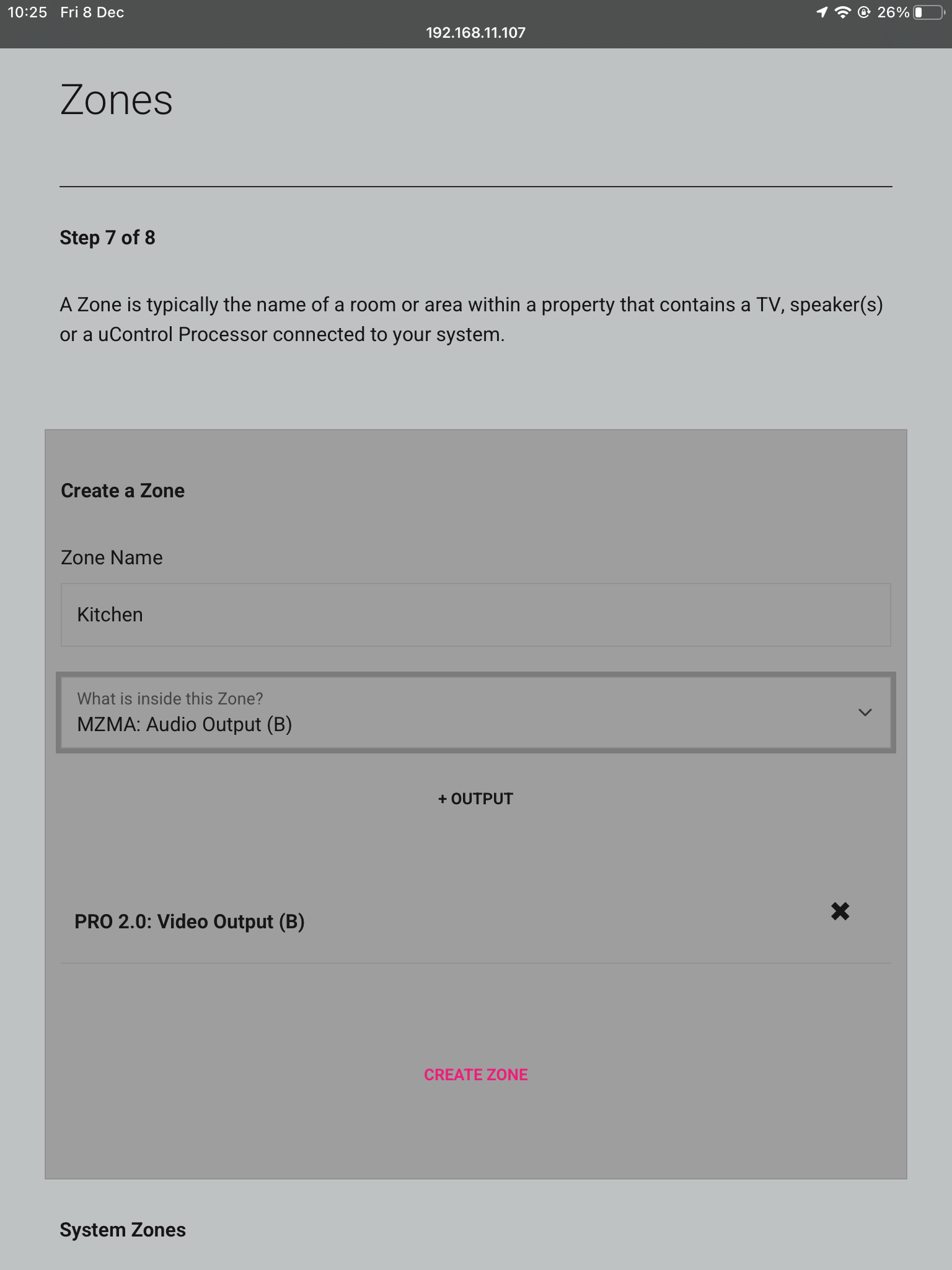
    13. Zones

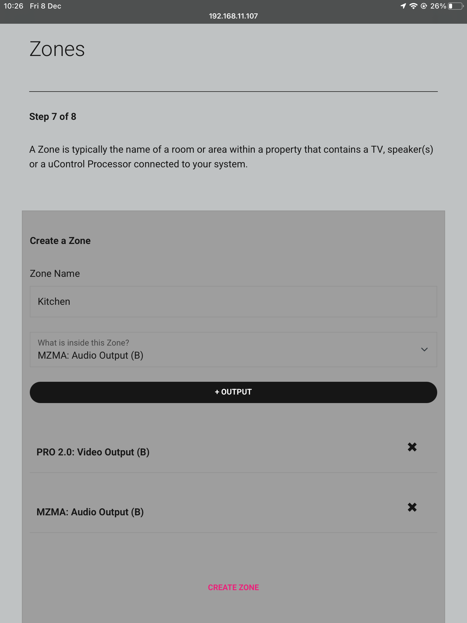
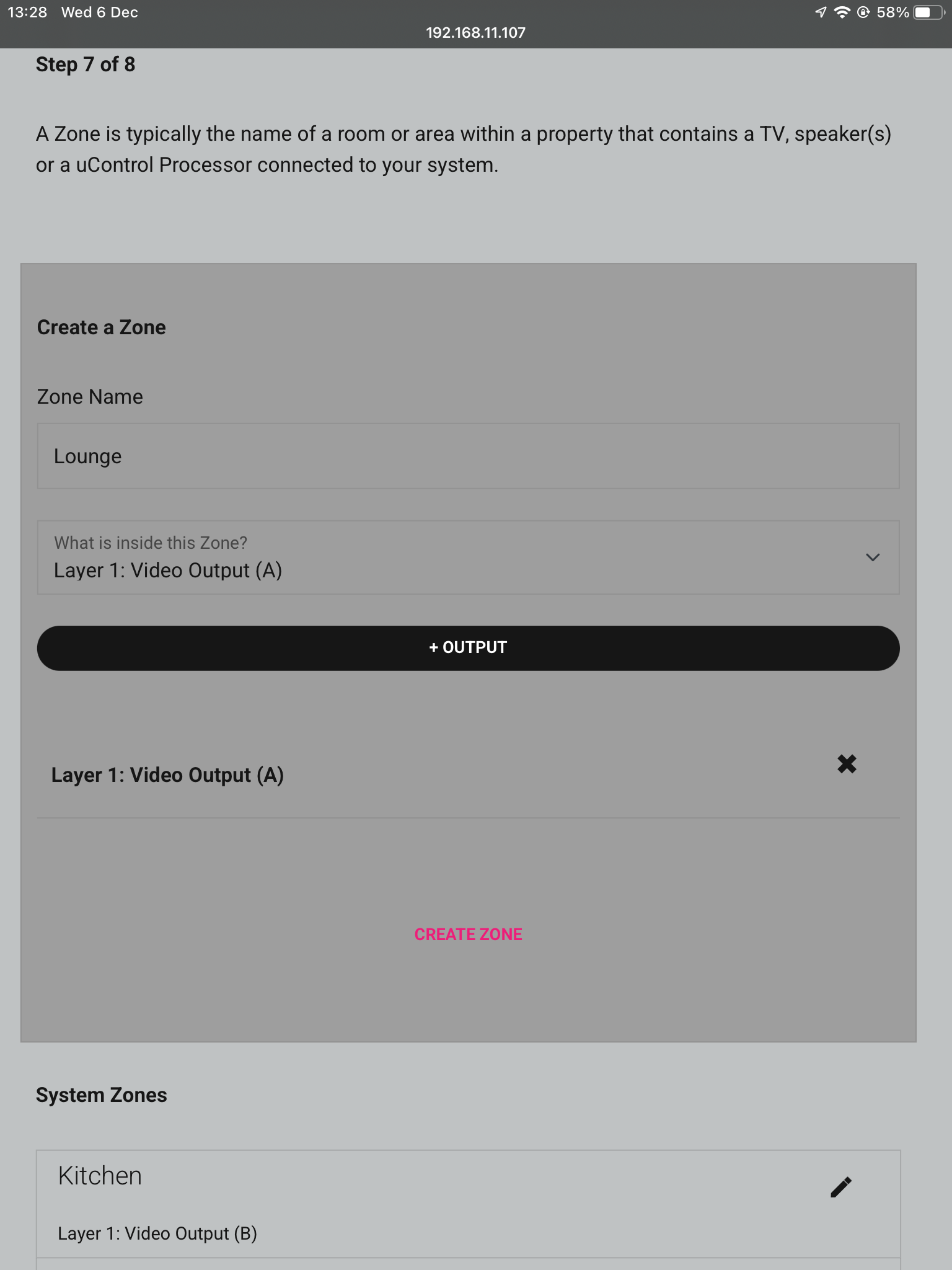
    Name the Zones after the rooms in the property which have the device(s) plugged into the corresponding ports. For example if the kitchen has the display plugged into Video Output (B) add this to that Zone, the same goes for the audio device Audio Output (B). To add your Outputs to the Zones select them from the dropdown box and then press +OUTPUT. Repeat these steps for all Outputs and Zones.

    13a. Zones

    Once you have added all Outputs to the zone it should look like below, press CREATE ZONE to finish.

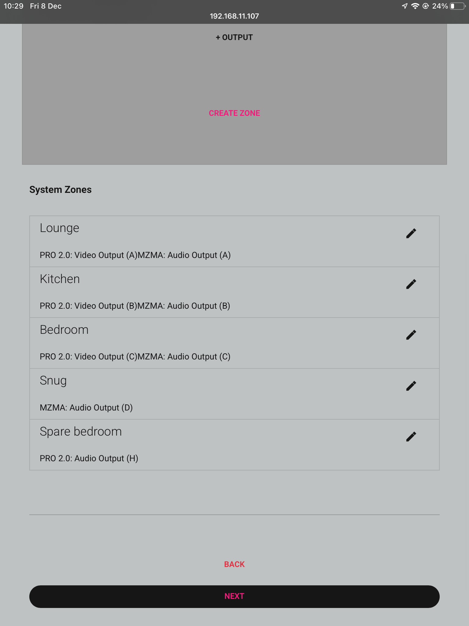
    13b. Zones

    Check over your zones and make sure you have assigned your devices to the correct zones.

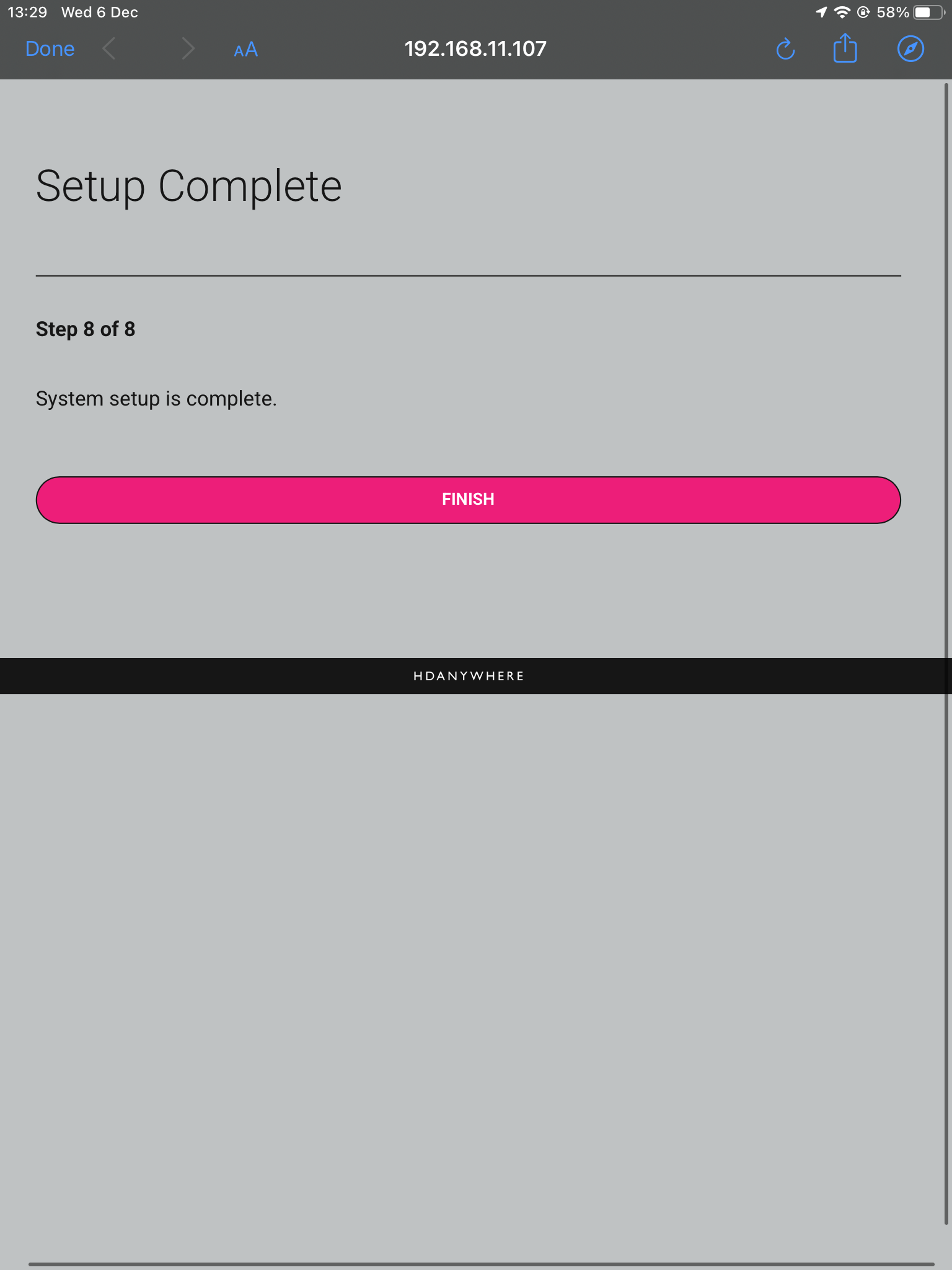
    14. Complete

    Now the system has been configured press “Finish” and you will be taken out of the web interface.

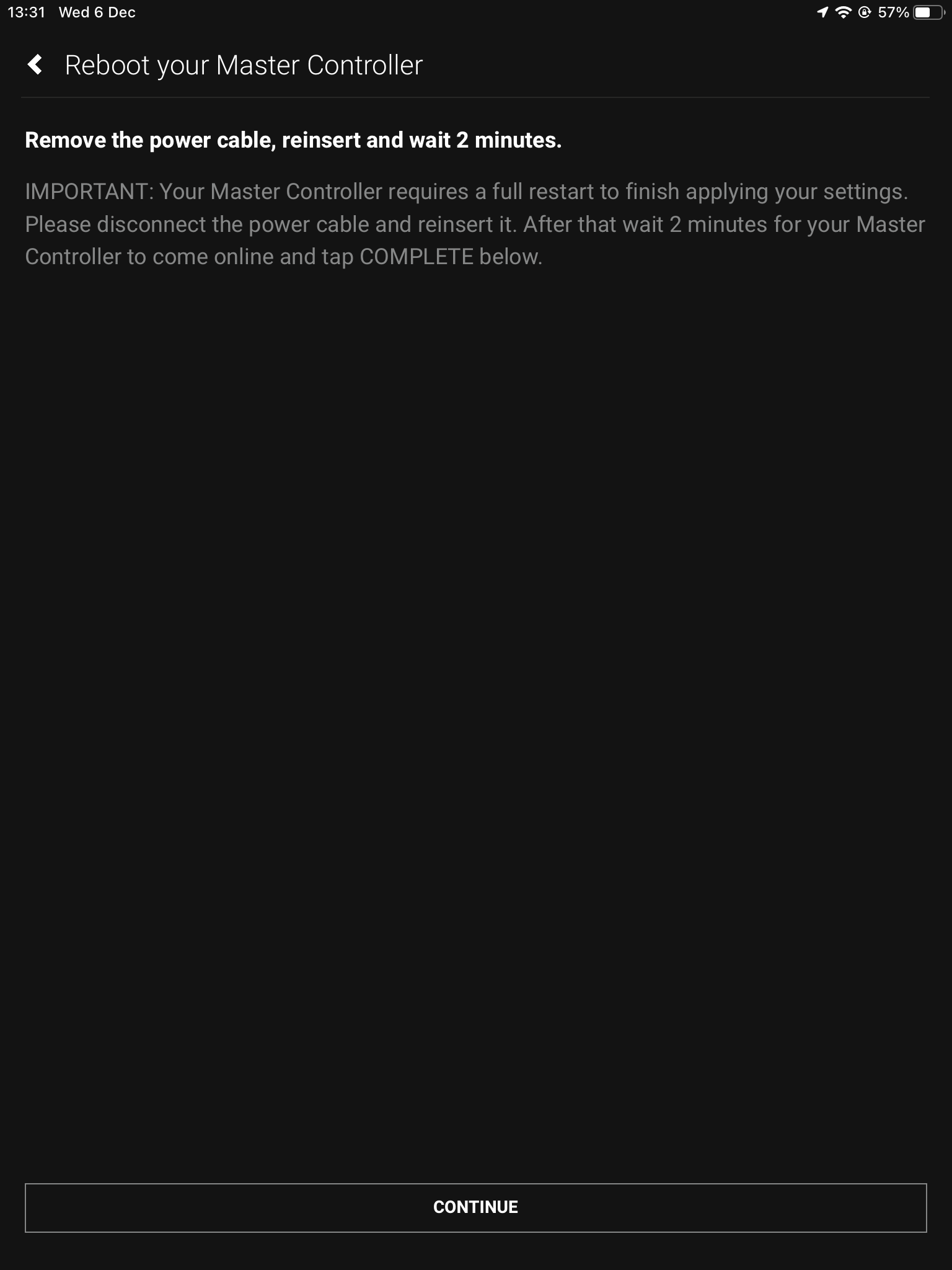
    15. Reboot

    The last step is to remove the power cable from your Zone Processor and wait 2 minutes, then plug it back in. This is needed to apply the settings you have just changed, once the 2 minutes is up press “Continue”.

    After hitting continue you will be taken into the uControl interface where you can begin setting up the necessary packs and additional features like Functions and Sequences. For more guides on setting up systems after the first boot, please refer to our uOS support page.


  • mHub 4K control system integration
    The mHub 4K range has full support for most popular control systems via serial (RS232) or IP.
    All control strings and current available drivers are available in the mHub control pack, available here – Download
    IP control

    To control the mHub 4k unit via IP you will first need to discover it by using the mHub controller software available in the control pack above

    The mHub 4K will acquire an IP address via DHCP the first time it is connected to your home network, use the controller software to locate it on your network.
    mhub controller pic 1

    In the mHub controller software select IP and then press the ‘search’ button, this should locate your mHub matrix. Press ‘connect’ the red button should turn green.

    Press the configure button

    mHub IP

    From here you can set the matrix to a static IP if you wish (this is generally good practice)

    Your matrix is now on your home network and will be able to receive IP commands from whatever control system you are using.

    Looking for the mHub 2K information, go here – mHub 2K

  • MHUB-OS 8 and uControl 2 update troubleshooting and FAQ

    Below is a list of three issues which have been reported to HDANYWHERE (HDA) after updating older systems to MHUB-OS 8 (MOS 8). If you have encountered any of these problems then you will find a solution below. If your issue is not shown below then contact the HDA support team via email on – support@hdanywhere.com.

    Jump to issues and solutions:

    1. My MHUB is stuck in a loop and is always prompting me to update again – I can not access any other MHUB-OS page.
    2. I am having problems connecting with HDA Cloud because there is an error with my serial number.
    3. I have connected to my MHUB and all my settings are gone.
    4. I can’t get uControl to connect to MHUB.
    5. I have an 8×8 system and I can not control my TVs anymore.

    1.
    I’ve clicked the update from within MHUB-OS and now appear to be stuck on an update page and cannot access any other MHUB-OS page.

    This error can occur when MHUB fails to complete the update process completely. This can be caused by a power outage, multiple sessions of MHUB-OS being open at the same time (browser tabs, app) or network issues as the update is applied to MHUB. This has been patched in version 8.02 of MHUB-OS. However, if you find yourself with a problem like this, you will need to contact HDANYWHERE technical support services by emailing support@hdanywhere.com with the subject line: “Update error code:728” and we will treat this with the highest priority.

    2.
    I’ve updated to MHUB-OS 8 and when linking to HDA cloud it says there is an error with my serial number.

    This error can occur when the MHUB cannot connect with HDA cloud. This can be caused by network issues or power outage. This has been patched in MHUB-OS version 8.02. However, should you find yourself in this situation you can recover the serial number following these steps

    1. Step 1 – Load a web browser on a pc or mac(such as Chrome), and enter the following in to the URL bar [MHUB IP ADDRESS]/diagnostics.php. Then click on “GET SERIAL NUMBER”
    2. Step 2 – Confirm that you want to change the serial number
    3. Step 3 – You will get a notifcation saying that the serial number has been updated, and should notice the serial number is showing in the system information section near the top of the page.

    If after using the serial number recovery method above, it still does not appear, you will need to contact HDANYWHERE technical support services by emailing support@hdanywhere.com with the subject line: “Update error code:628”

    3.
    uControl has updated, when I reconnected to my MHUB all my settings were gone.

    This can occur when reconnecting to your MHUB after uControl has updated to version 2 or greater and selecting the incorrect option. When uControl loads you are shown 2 options:

    • “SETUP A NEW MHUB SYSTEM” – This is used when you are connecting to a brand new or unconfigured MHUB system. If you select this option and have a previously configured system, all user data will be removed requiring the MHUB to be fully reconfigured like a new system.
    • “CONNECT TO AN EXISTING MHUB SYSTEM” – This is used when you are connecting to a previously configured MHUB system. Existing data will remain untouched, and uControl will sync the data stored. If you were connected with a previous version of uControl this option should be used.

    4.
    After the update, uControl can not connect to MHUB

    HDANYWHERE released an update to uControl and all MHUB systems on Wednesday 10th October 2018. To ensure that your MHUB works correctly both your MHUB and uControl must be on the correct software version.

    MHUB / MHUB-OS = version 8 or above
    uControl (iOS / Android) = version 2 or above

    If you find that one version of uControl can connect to MHUB and the other can not then it is very likely that you did not complete the update to MHUB-OS. As soon as you have run this process then uControl should work on all devices with no issue. For this solution HDANYWHERE are assuming that your system is already in a pre-configured state and that you are wanting to CONNECT TO AN EXISTING SYSTEM.

    Steps to resolve this issue:

    1. Ensure that you have the latest version of uControl installed on your iOS or Android device. Download uControl for iOS or download uControl for Android
    2. Once you have the app installed, please load it up and follow the instructions here:

    5.
    I have a 8×8 or 8×6+2 system and after the update, I lost the ability to control my TVs

    If you are able to control your source devices with uControl but can not control your displays then a quick update to your MHUB will resolve this problem. Instructions detailing how to update your MHUB can be found here. Ensure that you use uControl to update your MHUB and do not try to update your system via MHUB-OS.

  • Enabling DHCP on MHUB if you have lost it on your network

    If your MHUB has been configured with a fixed IP address and you changed your network infrastructure then your MHUB may become unreachable by your new router.

    With MHUB PRO models you can enable DHCP from the MENU button on the front panel by holding it down for 3 seconds. For MHUB 100A & MHUB U (4×1+1) 40 models you need to follow Guide 1, for MHUB U (4×3+1) 40 & (8×6+2) 40 models follow Guide 2 and for older MHUB U (micro USB on front) models use Guide 3.


    MHUB 100A & MHUB U (4×1+1) 40

    To reset DHCP on an MHUB (4×4, 6×6, 8+8×8) 100A you can either use the Hercules method which is included below, or you can hold down Output A on the front panel of the matrix for 10 seconds.

    To reset an MHUB S (16+16×16) 100A press and hold button 1 for 10 seconds.

    To reset to DHCP on an MHUB U (4×1+1) 40 you can press and hold the 2 front panel buttons for 10 seconds.

    Items needed

    Steps

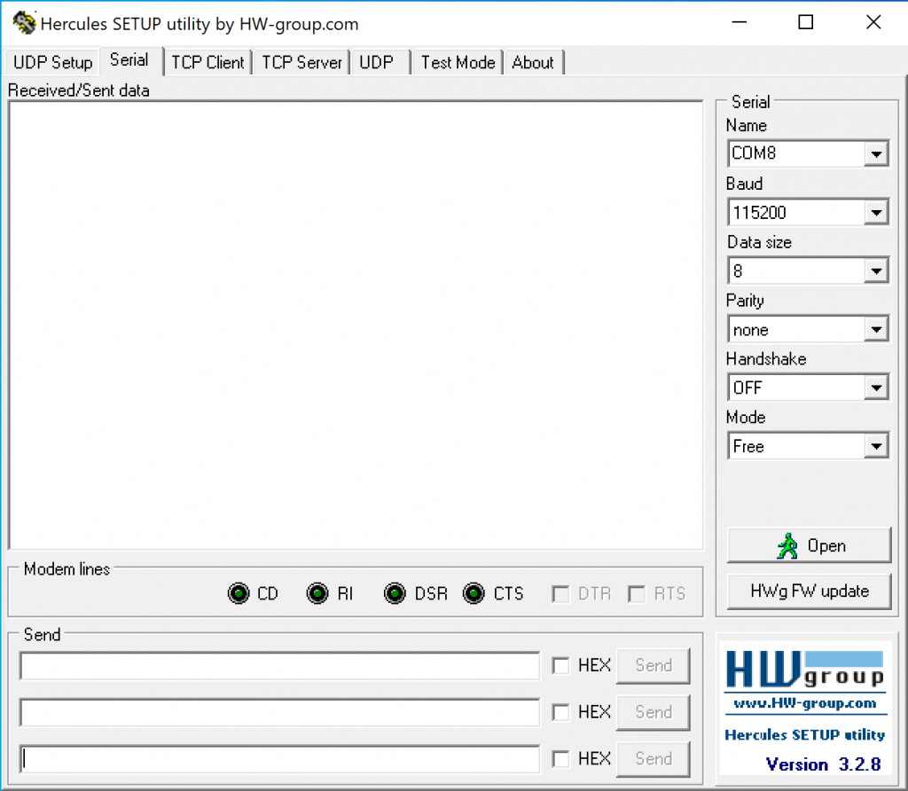
    1. Install Hercules and open the software on your PC or laptop
    2. Hercules interface

    3. Connect the serial to phoenix cable to the MHUB, and then your serial to USB adaptor into a laptop or PC.
    4. Go back to Hercules, ensure that the Baud is 115200, the Data Size is 8, the parity is None, the Handshake is OFF and finally, the Mode is Free.
    5. Click on the “Open” button. Your PC will now connect directly to the MHUB.
    6. Type DHCPON! in the box labelled “Send” and click “Send”. Make sure that “Hex” remains unticked.
    7. You will receive a response in the “Received/Sent Data” box. This will confirm that the MHUB has been reset to DHCP.
    8. Hard reboot your MHUB by pulling the power out from the back of the system.
    9. Reconnect MHUB to your router as normal and power up the system. Your MHUB should now be discoverable.

    MHUB U

    Items needed

    Steps

    1. Install Hercules and open the software on your PC or laptop
    2. Hercules interface

    3. Connect the serial to phoenix cable to the MHUB, and then your serial to USB adaptor into a laptop or PC.
    4. Go back to Hercules, ensure that the Baud is 115200, the Data Size is 8, the parity is None, the Handshake is OFF and finally, the Mode is Free.
    5. Click on the “Open” button. Your PC will now connect directly to the MHUB.
    6. Type DHCPON! in the box labelled “Send” and click “Send”. Make sure that “Hex” remains unticked.
    7. You will receive a response in the “Received/Sent Data” box. This will confirm that the MHUB has been reset to DHCP.
    8. Hard reboot your MHUB by pulling the power out from the back of the system.
    9. Reconnect MHUB to your router as normal and power up the system. Your MHUB should now be discoverable.

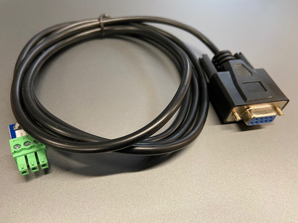
    Serial to phoenix Cable

    IMG_10May2021at131731


    MHUB 4K (with micro USB on front panel)
    If your MHUB U has a micro USB port on the right hand side of the front panel then please follow these steps to reset your system. Using Hercules from the steps above, send the following command:

    • Baud Rate 9600
    • Data Size 8
    • No parity
    • Restore Command: %0911. (include the full stop “.”)
    • Query IP Command: %9964.

  • Controlling AudioFlow from uOS

    This guide explains how to pull data from the Audioflow API so you can control it directly from uOS, uControl App and uControl Remote.


    Before you begin, you will need:

    Important: You must have the IP address for AudioFlow first

    You can get the IP address of your AudioFlow switch by:

    • Using a network scanner application like Fing on your mobile phone to scan your network.
    • Download the AudioFlow app and connect it to your network. From here go to settings, and you will see its IP address.

    Step 1 – Getting Data


    Step 2 – Build Function

    Need more help with the API? Get in touch.

    All HDA staff are able to help with any API questions you might have including any advanced features. Get in touch for help or assistance.

  • MHUB 100A and MZMA Stack

    Please read:

    This guide will show you how to build a stacked system using an MHUB (4×4)/(6×6) 100A and an MZMA (6×4) 55 with uControl acting as the main method of control for the system.

    Make sure the only HDA devices on the network are the ones you want to put into the Stacked System. If you still cannot discover them in the app consider your network infrastructure, the app may struggle to find the system(s) if there are things like network switches in the residence, so try simplifying it whilst going through setup.

    This guide is intermediate in difficulty and assumes that you have installed MHUB before in standalone mode.

    It is strongly recommended that you read this guide carefully before commissioning your stacked system to ensure all features of the system work as expected.

    25 minutes (approximately) to work through.

    What you will learn:

    Checklist

    To create a stacked system please make sure you have the following before you start:

    • MHUB (4×4) or (6×6) 100A
    • MZMA (6×4) 55
    • Zone Processor, uControl Connect (x1)
    • Audio cable(s) to create connections between your MHUB (4×4)/(6×6) 100A and MZMA (6×4) 55

    CHECK SOFTWARE VERSIONS:
    Check that ALL hardware above has been updated to the latest software version BEFORE you start configuration on uControl app.


    Glossary

    the following terms are used throughout this guide.

    Foundation Layer

    Foundation Layer

    The MHUB system which is directly connected to a video source(s) is referred to as the Foundation Layer. Ideally, this system should be physically installed at the bottom of your MHUB stack. Inside uOS this system is referred to as S1 (see Stack Layer below).

    Connections

    Connections

    A Connection is used to define the cabled connections between each component in an MHUB/MZMA Stack. The combination of HDA devices in your Stack will determine which ports can be paired or not.

    Stack Layer

    Stack Layer

    The Stack Layer is an alphanumeric identifier within uOS, starting from the Foundation Layer (Layer S1). This identifier represents the order of HDA systems that are connected to one another by a Connection. For example, if you had four HDA systems stacked together, then you would start with the Foundation Layer (Layer S1), then the second HDA device (Layer S2), followed by the third HDA device (Layer S3) and, finally, the fourth HDA device (Layer S4).

    Master / Controller

    Master / Controller

    An HDA device (like a Zone Processor) designed to control MHUB and/or MZMA (6×4) 55 systems operating in Stack mode. Any Stack that needs to be controlled by uControl must have a Master / Controller present in your setup. This is identified as M1 in uOS.

    uControl

    uControl

    uControl is our control system for configuration and control of stacked systems. When we refer to “uControl” in this article we are referring to our app specifically.


    Wiring

    A video and audio system is made possible by the audio ports on the back of the MHUB (4×4)/(6×6) 100A and MZMA (6×4) 55. Connect the 3.5mm Stereo port labelled Audio (In) on the back of the MZMA (6×4) 55 to the 3.5mm Stereo port on the back of the MHUB (4×4)/(6×6) 100A labelled Audio (Out).

    1. “Audio (OUT)”
      The audio ports on the back of the MHUB (4×4)/(6×6) 100A are labelled Audio (Out).
    2. “Audio (In)”
      The audio ports on the back of the MZMA (6×4) 55 are labelled Audio (In).
    Ports used in stack
    Figure 1: Showing stereo connection between MHUB (4×4)/(6×6) 100A and MZMA (6×4) 55.
    1. Connect your 3.5mm stereo cables to the Audio (In) port of the MZMA (6×4) 55 and repeat for every zone.
    2. Connect your 3.5mm stereo cables to the Audio (Out) port of the MHUB (4×4)/(6×6) 100A and repeat for every zone.
    3. Connect speakers via phoenix connector into the Audio (OUT) of the MZMA (6×4) 55 and repeat for every zone.
    4. Connect your HDBaseT/network cabling into the Video (OUT) of your MHUB (4×4)/(6×6) 100A then into your display receiver and repeat for each zone.
    fig2
    Figure 2: Wiring guide showing video and audio connection between MHUB (4×4)/(6×6) 100A and MZMA (6×4) 55(s).

    Watch video: How to wire MHUB (4×4)/(6×6) 100A and MZMA (6×4) 55 stack

    This video describes how to wire an MHUB (4×4)/(6×6) 100A with an MZMA (6×4) 55 to create a stack.


    Initialising your Stacked Video and Audio System using uControl

    Ensure that your MHUB (4×4)/(6×6) 100A and MZMA (6×4) 55 are correctly wired for stacking covered in the part above and that the following is completed:

    • Both MHUB (4×4)/(6×6) 100A and MZMA (6×4) 55 systems in your stack are powered ON.
    • Your Master / Controller device (Zone Processor or uControl Connect) is powered ON.
    • All HDA systems and the Master Controller are connected to the LAN and reachable by their IP address.
    • IMPORTANT: All hardware has been individually updated to the latest software version.

    Configuring MHUB (4×4)/(6×6) 100A and MZMA (6×4) 55 to operate in stacked mode cannot be undone without resetting the system and starting again. Ensure that you have your wiring information handy and that you know exactly how the system is connected together before initialising your stack.

    1. Connect to system

    To get started press connect to system on the uControl Homepage.

    2. Stack

    If the HDA devices are on the network you will be presented with the option to create a stack, video standalone or audio standalone, as this contains an MHUB (4×4)/(6×6) 100A and an MZMA (6×4) 55 choose stack.

    3. Master Controller

    The Zone Processor acts as the bridge between 2 or more HDA devices and all data goes through this device, acting as a brain. It needs to be selected as the Master Controller.

    4. Layers

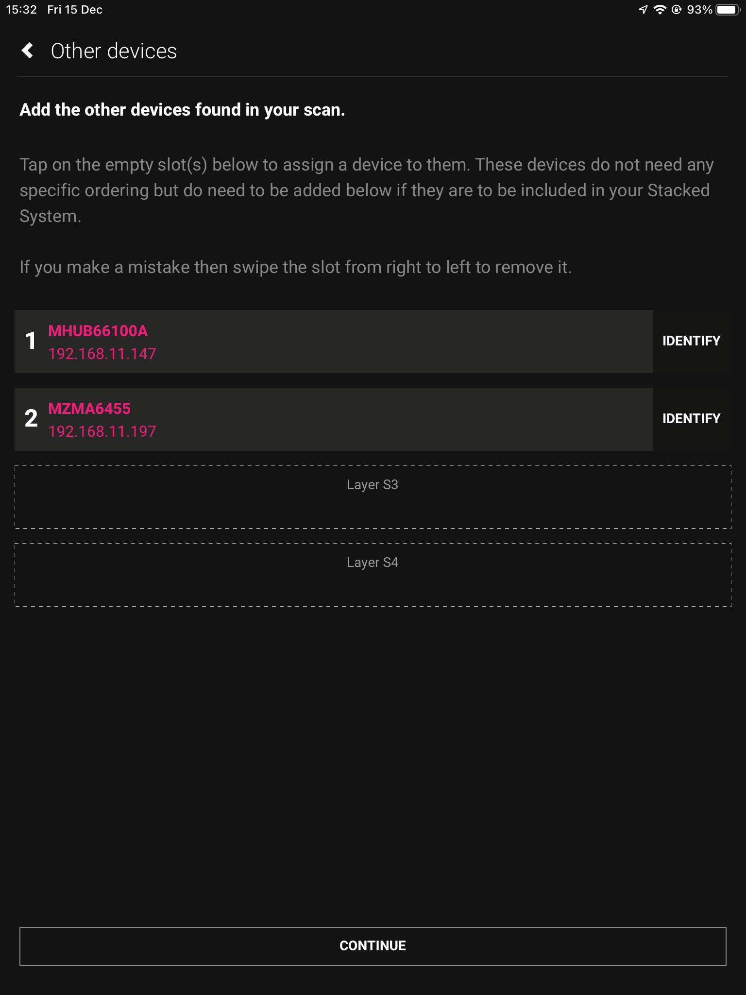
    Next we need to choose our layers, starting with the Foundation Layer. Press identify to the right of the HDA device to make the power LED blink, when you know which is which select your primary MHUB for 1 and the other HDA device for 2, then hit continue.

    5. Naming devices

    Now we have chosen where our devices go in the stack, we must name them so that they’re easily identifiable.

    6. Access uControl

    Assigning our hardware has now been complete, after pressing access uControl we will continue the setup in uOS.

    7. Cloud Account

    The first thing to do in uOS is to create a Cloud Account, or pair it to an existing one if possible. Cloud Accounts allow for Installers and HDA Tech Support to gather additional information regarding your systems performance.

    8. Control Type

    Choose uControl as Control Tyoe.

    9. System Name

    Confirm the names of your devices.

    10. Setup Connections

    This next step will allow us to make the manual connections between the multiple devices.

    11. Manual Connections

    This is where you tell the system how it is all linked. In this example Audio Output (A) is connected to Audio Input (1). For the second connection Audio Output (B) is connected to Audio Input (2). Repeat this step for every required connection.

    12. Naming Sources

    Name your inputs after what identifies them the easiest. This can be naming it after the specific source that is connected, or naming them incrementally.

    13. Zones

    A zone is where a display is located, so name the zones after the room those displays are in. To add an output to a zone, choose which output from the list and then press “+OUTPUT”, check that the output has been added below in bold and then press “Create Zone”. Repeat process for all zones.

    14. Complete

    Now the system has been configured press “Finish” and you will be taken out of the web interface.

    15. Reboot

    The last step is to remove the power cable from your Zone Processor and wait 2 minutes, then plug it back in. Ths is needed to apply the settings you have just changed, once the 2 minutes is up press “Continue”.

    After hitting continue you will be taken into the uControl interface where you can begin setting up the necessary packs and additional features like Functions and Sequences. For more guides on setting up systems after the first boot, please refer to our uOS support page.