Asides

  • Comparing HD matrices on a like-for-like basis

    matrix-like-for-like

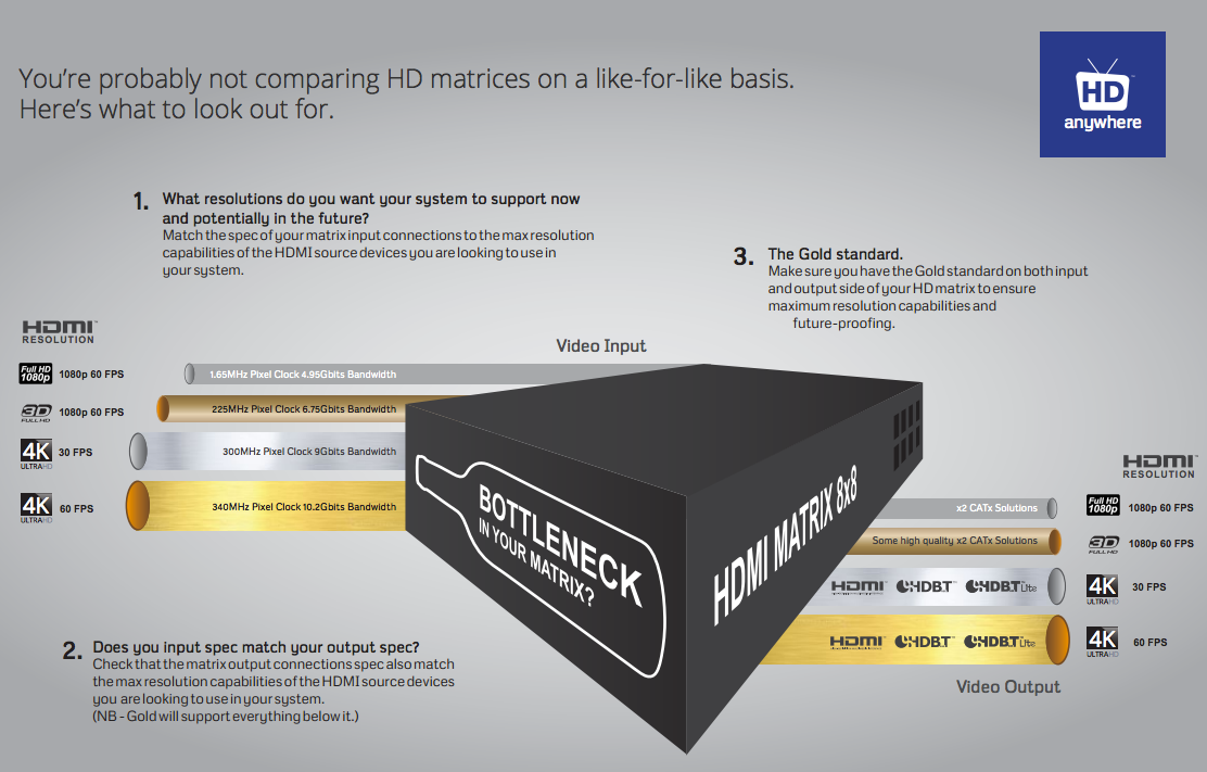
    Click here for enlarged image: matrix-comparison

    With all the technical jargon and various names given to 4K video, it’s difficult to properly compare HD matrices on a like-for-like basis. So here’s our HD matrix buyers guide to help simplify things.

     1. Ask yourself, what is the maximum resolution you want your system to support now and in the future?

    To help, you can look at the maximum resolution of your displays and / or HDMI sources that you want to connect to the HD matrix. To date, there are very few 4K sources, but lots of 4K capable displays. So you may only have 1080p sources, but 4K displays. So the choice is often if you would like 4K support from your HD Matrix or not, in order to future proof yourself for the eventual arrival of 4K capable source devices.

    To understand the resolutions in the table below in greater depth, you can click here for our more detailed 4K support article.

    Once you’ve decided on the support you’d like your HD matrix to have, you can match it off to the chipset specification required by studying the table below.

    This chipset specification can then be compared across HD matrix products. We’ve also broken the typcial chipset speeds down into levels to help make the next stage easier.

    (NB – Platinum will support all Gold resolutions, Gold will support all Silver resolutions and Silver will support all bronze resolutions.)

    Input Side Level

    Maximum Resolutions Supported

    Typical HDMI Chipset Specifications

    Platinum

    HDMI 2.0

    4096×2160 @ 60Hz 4:4:4

    600 Mhz Pixel Clock

    18 Gbits Bandwidth

    Gold

    HDMI 1.4

    3840×2160 @ 60Hz 4:2:0

    4096×2160 @ 30Hz 4:4:4

    1080p @ 60Hz 3D

    340 Mhz Pixel Clock

    10.2 Gbits Bandwidth

    Silver

    1080p @24Hz 3D

    1080p @ 60Hz

    720p @ 60Hz 3D

    165 Mhz Pixel Clock

    4.95 Gbits Bandwidth

    Bronze

    1080p @ 24Hz

    720p @ 60Hz

    1080i @ 60Hz

    75 Mhz Pixel Clock

    2.25 Gbits Bandwidth

    2. Therefore, which type of output technology do you need? 

    Next, it’s important to match your desired resolution support to an output technology level that supports that resolution. So you can match gold to gold for example from the previous table.

    Once you’ve chosen the appropriate level, there can be multiple types of output technology at the same level. So your choice between them may be based on features other than resolution capability. For a full breakdown of the different types of output technology on offer and their key features, you can read our article here.

    You can then compare HD matrices looking for the required or your chosen technology.

    (NB – Platinum technology will support all Gold technology resolutions, Gold technology will support all Silver technology resolutions and Silver technology will support all bronze technology resolutions.)

    Output Side Level

    Maximum Resolutions Supported

    Output Technology Choices

    Platinum

    4096×2160 @ 60Hz 4:4:4

    Native HDMI 2.0

    Gold

    3840×2160 @ 60Hz 4:2:0

    4096×2160 @ 30Hz 4:4:4

    1080p @ 60Hz 3D

    All Platinum Choice and:

    Native HDMI 1.4 (High Speed)

    HDBaseT-Pro (100m CATx Soltution)

    HDBaseT-Lite (70m CATx Solution)

    Silver


    1080p @24Hz 3D

    1080p @ 60Hz

    720p @ 60Hz 3D

    All Platinum and Gold Choices plus:

    Some high quality (non-HDBT) SingleWire & TwinWire 2x CATx solutions. Such as the HDAnywhere mHub.

     Bronze

    1080p @ 24Hz

    720p @ 60Hz

    1080i @ 60Hz

    All Platinum, Gold and Silver Choices.

    3. Lastly, make sure your matrix doesn’t have a bottleneck.

    A HD Matrix is most commonly made up of three main stages. The input stage, the multiplexing stage and the output stage.

    It’s vital to check that each stage of the matrix has the same chipset capability or resolution capability. Most manufacturers will list the chipset speeds they are using and will group together the input stage and the multiplexing stage. Always seek clarification if this is not clear.

    Some HD Matrices will have a Gold level input specification, but a silver level output. The result of this is that whilst you may be able to send into the HD matrix a 4K signal (such as 3840×2160 @ 60Hz 4:2:0) you cannot output it from the HD matrix to a TV. So the HD matrix does not have 4K support throughout.

    If you work through the above and check in enough detail, you should get what you expect from your HD matrix purchase.
     

  • Troubleshooting: IR over HDMI Kit

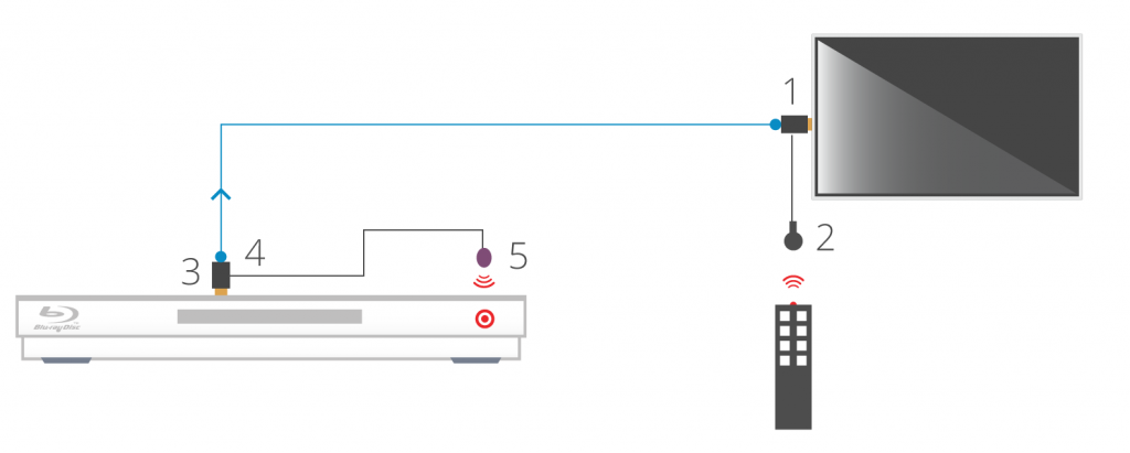
    NB: Both dongles have ‘RX’ moulded into the casing.

    When using the IR over HDMI function, ensure that the switch is pushed across to ‘IR’ and not ‘CEC’.

    Connect the dongles into the source device’s HDMI output port and the display device’s HDMI input port, initially without the HDMI cable connected.

    Connect the IR cables. Connect the IR TX cable to the dongle that’s connected to the source device and connect the IR RX cable to the dongle connected at the display.

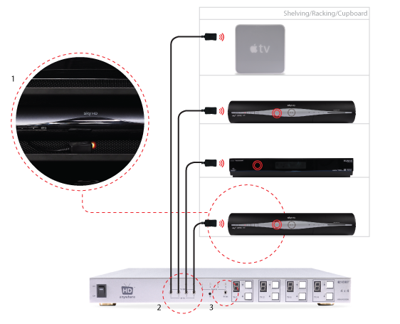
    In order to use your source device remote(s) at the TV location, ensure that the IR RX cable receiver eye is fully inserted into the 3.5mm jack port on the dongle and the IR RX cable magic eye is positioned in sight of where you would usually like to point the remote control(s).

    Connect the IR TX emitter cable to the 3.5mm jack port on the source device dongle and position the IR emitter in sight of the IR receiving window on that connected source device.
    TIP: tape the TX cable flat to a piece of card sat under the source device pointing at the IR window

    When using the IR over HDMI kit is set-ups involving splitters/switches/matrices, remember that the IR dongle has to be connected at either ends of a single HDMI cable run. So the dongle will be connected to the HDMI output port of the splitter/switch/matrix and not the HDMI output of the source device. To control the desired source device(s) – ensure that the IR TX emitter cable is positioned in sight of the IR receiving window on that connected source device.

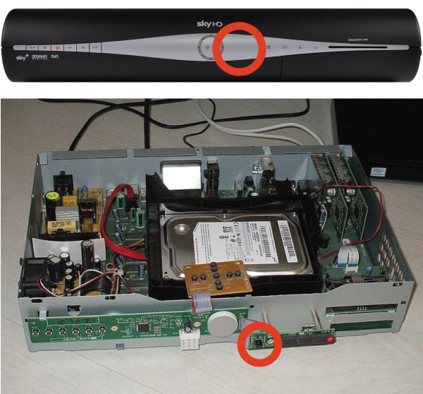
    The exact position of the IR window can vary between makes and models of source. Generally it is on the left hand side about 2 inches from the middle of the box. Often it can be a bit of trial and error to locate the optimum IR emitter placement position. Once found I would advice taping/fixing the emitter in place.

    A final tip is to ensure that the batteries in your remote control are at full strength. (It’s amazing how a fresh set of batteries can resolve weak IR issues).

    If you have all this in place and are still experiencing issues, please contact Customer Services

  • HDanywhere Multiroom+ PoE and 4×4 V3 System IP Software

    The Multiroom+ PoE and 4×4 V3 systems have a user accessible web page built into them. This web page has an address that you type into a web browser (such as internet explorer or Google Chrome) and it allows you to control the matrix as well as change settings to do with the central hub.

    All of the multiroom+ PoE and 4×4 V3 units ship with these default network settings:

    IP Address: 192.168.1.88
    Subnet mask:255.255.255.0
    Default gateway:192.168.1.1

    In most cases these will need to be changed to work with the network the central hub is connect to.

    To achieve this, you first need to connect the central hub LAN port on the rear of the main hub to a Lan socket on your home network hub or router. Once this has been done, you need to discover the central hub on your network.

    Once this software is installed on your PC, you’ll be able to discover and set the central hubs’ network settings. Instructions on how to do so are included in the associated system manual.

    Please follow the link below to download the software:

    HDanywhere Multiroom+ 4×4 PoE IP Software

  • Using the HDC Trade Modular System Builder

    The Modular System Builder is an invaluable tool when you need to get a quote or setup a Modular system quickly and correctly. But before you do start configuring your system make sure that you note the following:

    1. The Modular Chassis options for the 4×4 and 8×8 have different power requirements.
      1. The 4×4 can be fitted with an optional PSU module if a redundant power supply option is needed. It’s should be set to 1 as a default.
      2. The 8×8 has its power supplies built in to the unit. There is no need to add any if you are specc’ing one of these.
    2. IEC power cables
      1. You will need x1 cable per PSU module, again the default should be set to 1
      2. 8×8’s will require x2 IEC cables are the main unit contains two power supplies
    3. Blank plates for unused ports can only be added to 8×8 systems
    4. Forwards IR is only supported by the 8×8 and needs additional configuration – please call us 01684 576 348 if you need this functionality or contact us.
    5. IR hardware is sold as an individual units, you will need to add as many transmitters and receivers as you need, HDMI Input/Output modules do not support IR Passback
    6. HDanywhere SmartControls are pre-programmed to operate with the Modular Chassis included in the builder.
  • Troubleshooting: Multiroom+ System IR

    Troubleshooting Approach

    When attempting to troubleshoot any issue, we need to isolate where the root cause of the fault could lie by a logical process of elimination.

    At the start of a troubleshooting process, never rule out anything as not a potential cause of the problem. Every aspect of the installation should be considered as a potential suspect. Each component of the installation should be ruled out one-by-one and only then eliminated from the troubleshooting process as the potential problem.

    (more…)

  • Control Drivers for 4×4 Multiroom+ POE System (IP / RS232 / IR) – HKHDA44P

    Control Drivers for 4×4 Multiroom+ and POE System –  HKHDA44P

    We have ready-made control system drivers available for the 4×4 Multiroom+ Version 3 and POE Systems for the major control systems used in the UK. These are either IP, IR or RS232 Based.

    Each download package for Control4, AMX, Crestron and RTI also includes support for the 4×4 HDMI Matrix (HKM44-UK, both V1 and V2), 4×4 Multiroom+ Singlewire (HKHA414SW, V1, V2 and V3) and the Multiroom+ 8×8 System (HKHA818SW).

    (more…)

  • Locating the IR window on common HDMI devices

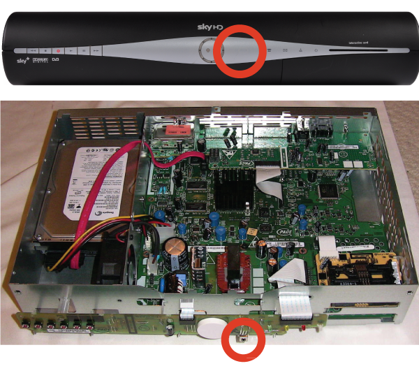
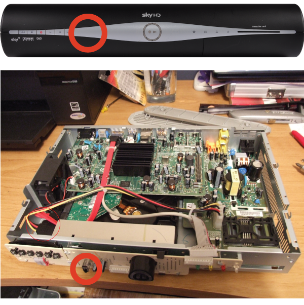
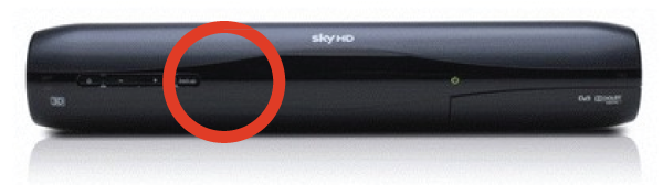
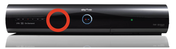
    Finding the IR window on your source device can be difficult if it isn’t mentioned in your user manual or is marked clearly on the front of your device. A very common device is Sky+HD and Virgin’s Tivo boxes. Below, we’ve marked where the IR windows are on these devices for easy installation.

    THOMSON model DSI8215


    PACE model TDS850NB


    Amstrad model DRX895


    Sky multiroom box

    Sky HD Terabyte box


    Can’t find the source device that you we’re looking for? Please email us with a request and we will make it available online the next working day.

    Still having problems with your IR setup?
    Please check our HDanywhere IR wiring setup diagrams or have a look at our IR troubleshooting video

  • HKIRKIT-UK: IR over HDMI Injector Kit setup guide

    ir-magic-eye-1

    IR over HDMI Injector Kit setup guide

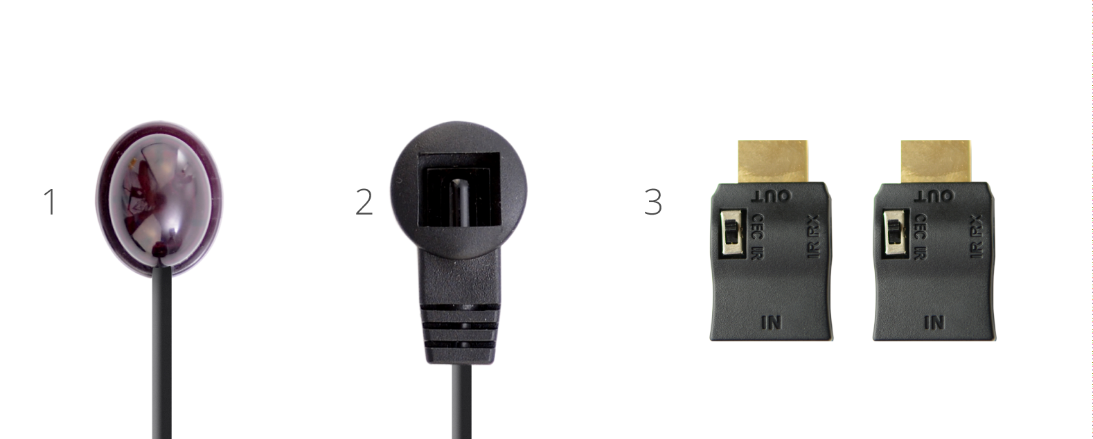
    1. Install the HDMI IR dongle between the HDMI input on the TV and your HDMI cable. Ensure that the switch is set to “IR”. Plug the IR Receiver (see ‘Pack Contents – 2.’) into the stereo jack input on the dongle (labelled RX).
    2. Position the IR Receiver ( see ‘Pack Contents – 2.’) with clear line-of-sight to the remote.
    3. Install the HDMI IR dongle betwen the HDMI input on the source and the HDMI cable, similarly to point 1. Again, ensuring that the switch is set to “IR”.
    4. Plug the IR Transmitter (see ‘Pack Contents – 1.’) into the stereo jack input on the dongle (labelled RX on the dongle).
    5. Position the IR transmitter ( see ‘Pack Contents – 1.’) with clear line-of-sight to the remote receiver on the source.e.

    Pack Contents

    1. IR Transmitter
    2. IR Receiver
    3. IR Dongle (both labled RX)

    ir-magic-eye-2

    You can download this information by clicking here

  • What do the flashing lights on my HDBaseT receivers mean?


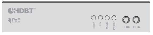
    1. HDCP indictor light – shows whether a handshake between that display and source has been authenticated

    2. Link indicator light – confirms the TV receiver is connected to the hub

    3. Mode indicator light – if flashing all is correct

    4. Power indicator light – Lit when the TV receiver is on