Category: Matrixes

  • Comparing HD matrices on a like-for-like basis

    matrix-like-for-like

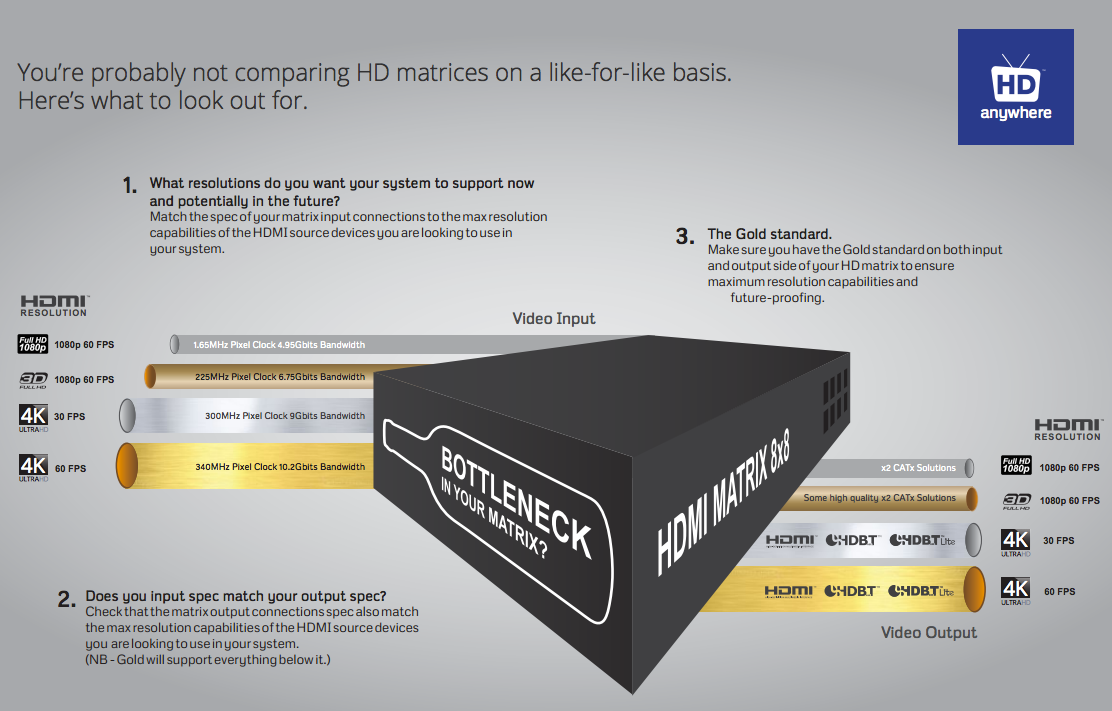
    Click here for enlarged image: matrix-comparison

    With all the technical jargon and various names given to 4K video, it’s difficult to properly compare HD matrices on a like-for-like basis. So here’s our HD matrix buyers guide to help simplify things.

     1. Ask yourself, what is the maximum resolution you want your system to support now and in the future?

    To help, you can look at the maximum resolution of your displays and / or HDMI sources that you want to connect to the HD matrix. To date, there are very few 4K sources, but lots of 4K capable displays. So you may only have 1080p sources, but 4K displays. So the choice is often if you would like 4K support from your HD Matrix or not, in order to future proof yourself for the eventual arrival of 4K capable source devices.

    To understand the resolutions in the table below in greater depth, you can click here for our more detailed 4K support article.

    Once you’ve decided on the support you’d like your HD matrix to have, you can match it off to the chipset specification required by studying the table below.

    This chipset specification can then be compared across HD matrix products. We’ve also broken the typcial chipset speeds down into levels to help make the next stage easier.

    (NB – Platinum will support all Gold resolutions, Gold will support all Silver resolutions and Silver will support all bronze resolutions.)

    Input Side Level

    Maximum Resolutions Supported

    Typical HDMI Chipset Specifications

    Platinum

    HDMI 2.0

    4096×2160 @ 60Hz 4:4:4

    600 Mhz Pixel Clock

    18 Gbits Bandwidth

    Gold

    HDMI 1.4

    3840×2160 @ 60Hz 4:2:0

    4096×2160 @ 30Hz 4:4:4

    1080p @ 60Hz 3D

    340 Mhz Pixel Clock

    10.2 Gbits Bandwidth

    Silver

    1080p @24Hz 3D

    1080p @ 60Hz

    720p @ 60Hz 3D

    165 Mhz Pixel Clock

    4.95 Gbits Bandwidth

    Bronze

    1080p @ 24Hz

    720p @ 60Hz

    1080i @ 60Hz

    75 Mhz Pixel Clock

    2.25 Gbits Bandwidth

    2. Therefore, which type of output technology do you need? 

    Next, it’s important to match your desired resolution support to an output technology level that supports that resolution. So you can match gold to gold for example from the previous table.

    Once you’ve chosen the appropriate level, there can be multiple types of output technology at the same level. So your choice between them may be based on features other than resolution capability. For a full breakdown of the different types of output technology on offer and their key features, you can read our article here.

    You can then compare HD matrices looking for the required or your chosen technology.

    (NB – Platinum technology will support all Gold technology resolutions, Gold technology will support all Silver technology resolutions and Silver technology will support all bronze technology resolutions.)

    Output Side Level

    Maximum Resolutions Supported

    Output Technology Choices

    Platinum

    4096×2160 @ 60Hz 4:4:4

    Native HDMI 2.0

    Gold

    3840×2160 @ 60Hz 4:2:0

    4096×2160 @ 30Hz 4:4:4

    1080p @ 60Hz 3D

    All Platinum Choice and:

    Native HDMI 1.4 (High Speed)

    HDBaseT-Pro (100m CATx Soltution)

    HDBaseT-Lite (70m CATx Solution)

    Silver


    1080p @24Hz 3D

    1080p @ 60Hz

    720p @ 60Hz 3D

    All Platinum and Gold Choices plus:

    Some high quality (non-HDBT) SingleWire & TwinWire 2x CATx solutions. Such as the HDAnywhere mHub.

     Bronze

    1080p @ 24Hz

    720p @ 60Hz

    1080i @ 60Hz

    All Platinum, Gold and Silver Choices.

    3. Lastly, make sure your matrix doesn’t have a bottleneck.

    A HD Matrix is most commonly made up of three main stages. The input stage, the multiplexing stage and the output stage.

    It’s vital to check that each stage of the matrix has the same chipset capability or resolution capability. Most manufacturers will list the chipset speeds they are using and will group together the input stage and the multiplexing stage. Always seek clarification if this is not clear.

    Some HD Matrices will have a Gold level input specification, but a silver level output. The result of this is that whilst you may be able to send into the HD matrix a 4K signal (such as 3840×2160 @ 60Hz 4:2:0) you cannot output it from the HD matrix to a TV. So the HD matrix does not have 4K support throughout.

    If you work through the above and check in enough detail, you should get what you expect from your HD matrix purchase.


  • Troubleshooting: “No picture on one of the TVs connected to my matrix”

    In order to effectively troubleshoot this problem, we need to deduce whether or not the matrix, the HDMI cables, extender set, or other connectivity accessories such as wallplates, repeaters or cable joiners are at fault.

    Troubleshooting Step 1

    Swap the outputs over on the matrix to see whether the problem follows the cable run, or stays associated with the HDMI port. This will help us decide whether it is the cable run or the matrix at fault.

    Outcome 1: Problem follows the cable.

    You have isolated the issue to be associated with that particular cable run and TV. If possible, try an alternative HDMI cable (such as the one connected to another TV on the matrix) to deduce whether a known to be working cable solves the issue. If it does, there is a good chance that the original HDMI cable is at fault and requires replacing.

    Outcome 2: Problem stays with the port on the matrix.

    You have isolated the issue to be associated with that particular HDMI port on the matrix. This issue could be hardware or software related.

    Firstly, to rule out whether it is a software issue, follow the hard reset procedure (described in manual) to reset the matrix software. If this does not revive the troublesome HDMI port, it is likely that there is a hardware fault with the matrix.

    In this case, Contact Customer Services. for a replacement unit.

  • Troubleshooting: Mixing 3D and 2D on a matrix or splitter

    In order to route 3D content easily via a matrix switch or splitter, ALL connected displays need to be 3D compatible. Even, if just one of the displays is not 3D compatible, the 3D source player will NOT output the 3D content. The HDMI handshaking process will trigger the source player to drop it’s resolution output so that all displays can show content.

    The problem is HDMI is designed such that the source ‘polls’ the EDID data (EDID is a display’s identity card stating what it’s capabilities are, a bit like a top trumps card) from all connected Sink devices (your 3D enabled display and non-3D enabled AVR) and outputs the lowest quality video signal all devices support (2D in your case).

    To ensure 3D IS routed via the Matrix Switch or Splitter, the non-3D compatible display device must not be ‘active’. Sometimes turning the display into standby will be sufficient and sometimes full power off is required.

    Essentially, the 3D source player must not be able to ‘see’ a 2D only display connected to the Matrix Switch or Splitter.

    For best results when using 3D Blu-ray – HD Connectivity recommends… not actually connecting your 3D Blu-ray (BR) player to the Matrix. As Blu-ray 3D content is generally only viewed at a single ‘main’ TV location, in this instance it is better to have a direct connection between source and display, bypassing the Matrix completely. This will avoid any potential for ‘black screen’ situations at the other TV locations. It will also ensure that absolutely the best 3D format is selected for use on that display, not a potentially reduced quality 3D format that a lower 3D-capable display, connected to the matrix can influence the 3D BR to output. (Plus wearing those massive 3D glasses all around your house is really not cool and could result in you bumping into doorframes! – Ed)

  • Hard reset device back to factory condition

    If you have been advised to ‘hard reset’ your HDanywhere device back to it’s factory condition, please perform the following.

    A hard reset will clear any corrupted DDC, EDID or HDCP data on the device’s NVRAM memory and re-initiate the handshaking process with all the connected devices.

    Firstly we need to ensure that any manufacturer HDMI CEC link protocols are switched to “off”.

    Trade names for CEC are Anynet+ (Samsung); Aquos Link (Sharp); BRAVIA Link and BRAVIA Sync (Sony); HDMI-CEC (Hitachi); E-link (AOC); Kuro Link (Pioneer); CE-Link and Regza Link (Toshiba); RIHD (Remote Interactive over HDMI) (Onkyo); RuncoLink (Runco International); SimpLink (LG); HDAVI Control, EZ-Sync, VIERA Link (Panasonic); EasyLink (Philips); and NetCommand for HDMI (Mitsubishi)

    To perform the hard reset:

    Power down every device in the set-up – that’s all sources, all displays and the device itself. Leave off at the mains for 10 to 15 minutes.

    Now switch all connected display devices on and select the HDMI channel on those displays.

    Power the device back on at the mains.

    Now one by one, power on the source devices, starting with input 1, input 2 and so on. If you are using a cable/satellite receiver such as Virgin or Sky+HD, please ensure that this is connected to input 1, not input 2. Please note that Sky HD boxes take around two minutes to fully reboot.

    After a few seconds everything should have synced and shaken hands correctly and normal operation should resume.

    If the problem still persists, Contact Customer Services. for further troubleshooting advice.

  • Troubleshooting: IR over HDMI Kit

    NB: Both dongles have ‘RX’ moulded into the casing.

    When using the IR over HDMI function, ensure that the switch is pushed across to ‘IR’ and not ‘CEC’.

    Connect the dongles into the source device’s HDMI output port and the display device’s HDMI input port, initially without the HDMI cable connected.

    Connect the IR cables. Connect the IR TX cable to the dongle that’s connected to the source device and connect the IR RX cable to the dongle connected at the display.

    In order to use your source device remote(s) at the TV location, ensure that the IR RX cable receiver eye is fully inserted into the 3.5mm jack port on the dongle and the IR RX cable magic eye is positioned in sight of where you would usually like to point the remote control(s).

    Connect the IR TX emitter cable to the 3.5mm jack port on the source device dongle and position the IR emitter in sight of the IR receiving window on that connected source device.
    TIP: tape the TX cable flat to a piece of card sat under the source device pointing at the IR window

    When using the IR over HDMI kit is set-ups involving splitters/switches/matrices, remember that the IR dongle has to be connected at either ends of a single HDMI cable run. So the dongle will be connected to the HDMI output port of the splitter/switch/matrix and not the HDMI output of the source device. To control the desired source device(s) – ensure that the IR TX emitter cable is positioned in sight of the IR receiving window on that connected source device.

    The exact position of the IR window can vary between makes and models of source. Generally it is on the left hand side about 2 inches from the middle of the box. Often it can be a bit of trial and error to locate the optimum IR emitter placement position. Once found I would advice taping/fixing the emitter in place.

    A final tip is to ensure that the batteries in your remote control are at full strength. (It’s amazing how a fresh set of batteries can resolve weak IR issues).

    If you have all this in place and are still experiencing issues, please contact Customer Services

  • Troubleshooting: Multiroom+ System IR

    Troubleshooting Approach

    When attempting to troubleshoot any issue, we need to isolate where the root cause of the fault could lie by a logical process of elimination.

    At the start of a troubleshooting process, never rule out anything as not a potential cause of the problem. Every aspect of the installation should be considered as a potential suspect. Each component of the installation should be ruled out one-by-one and only then eliminated from the troubleshooting process as the potential problem.

    (more…)

  • How to disable the beep on mHub 2K and 4K (4×4 and 8×8)

    To disable the beep on the mHub 2k range of matrices please following the instructions below using either I.P or RS232 connection methods.

    To adjust the settings on the mHub range of products, you will need to download the controller software Download

     A) Connecting to the mHub Via I.P

    The mHub 2K’s IP address is pre-configured as 192.168.0.100, your computer will need to have it’s IPV4 range configured to be within the same range initially while you setup the matrix. (You don’t need to follow this step if you have a mHub 4K system)

    To configure your IPV4 settings you will need to navigate to the following menu

    ->Network and sharing center

    —>Ethernet
    —–>Properties
    ——->Internet Protocol Version 4 (TCP/IPv4)
    ———>Properties

    IPV4

    Once you have changed the IP settings on your PC, open the Mhub controller software.

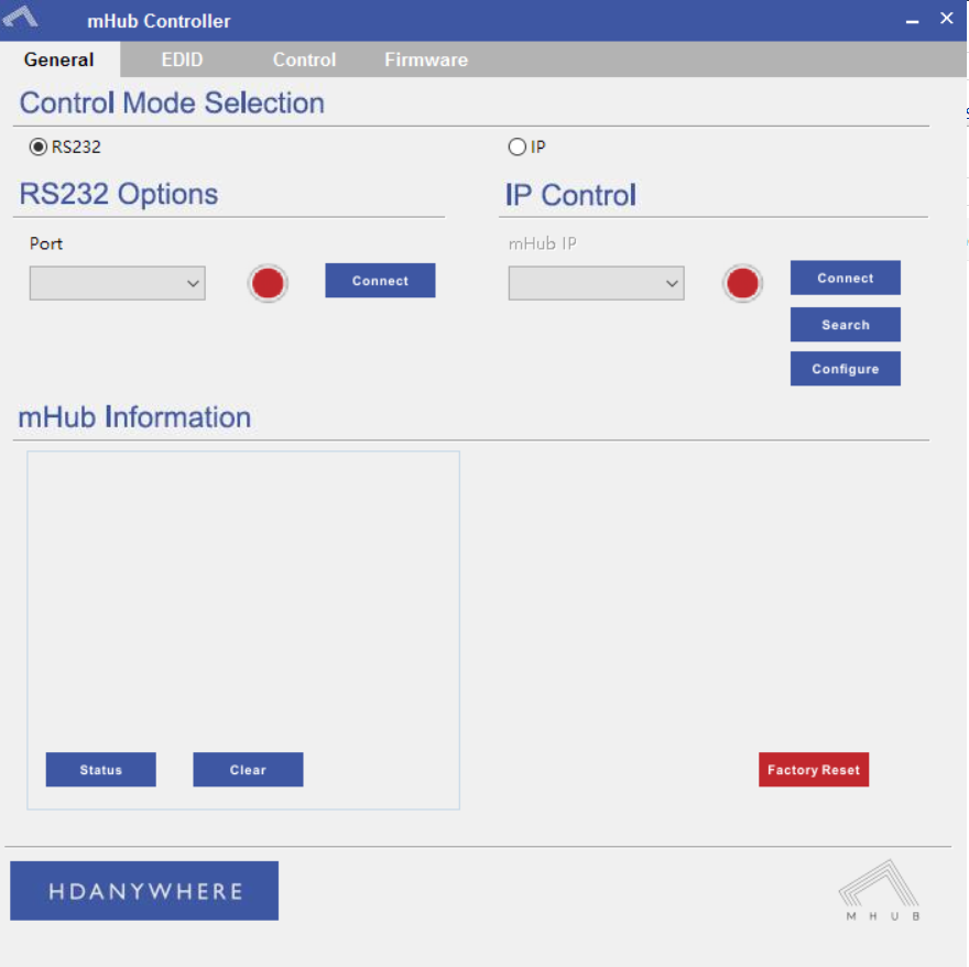
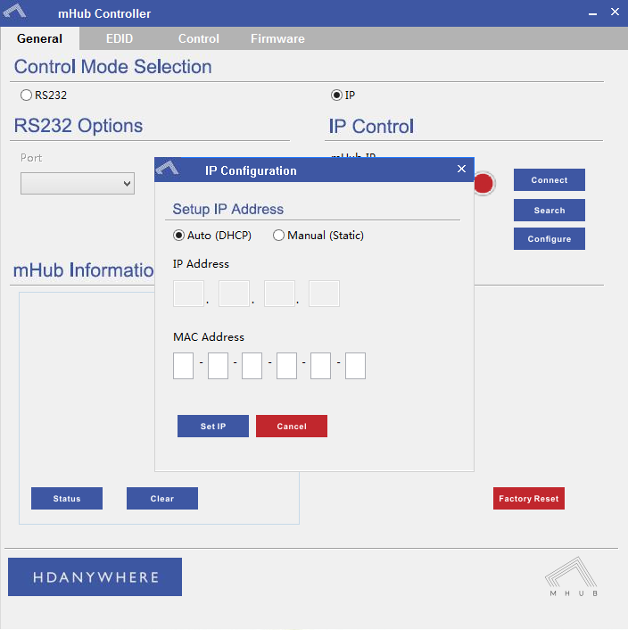
    In the Control Mode Select Box choose ‘IP’, then click the ‘Search’ button. When the IP address shows in the mHub IP box, click connect.


    B)  Connecting to the mHub Via RS232

    To connect via RS232 use the supplied serial cable can connect between the mHub and your PC, then on the Controller software select ‘RS232’, then in the RS232 Options section select the Com port being used from the drop down menu then click connect

    Capture


    C) Disabling the Beep

    To disable the beep select the ‘Control’ tab and untick the box labeled ‘Enable Feedback Beep’.

    mHubbeepimage

    Once changed, you can verify the beep has been disabled by performing a source switch operation.

  • Software configuration tool for MHUB 2K and MHUB 4K (2014-2016)

    Windows configuration tool for MHUB 2K and MHUB 4K systems. Search for MHUB, configure EDID and network settings.

    Download the MHUB 2K and MHUB 4K configuration tool.

    The software configuration tool has been written for an older version of Windows. If you run the exe file on your laptop and you receive a C++ error message then please read this support article.

  • Daisy Chaining IR – How To

    Daisy chaining IR can allow you to connect the IR systems of 2 devices. This allows IR to pass from one device to another

    This does not work for HDMI Mirrored ports.

    a) The diagram below shows how you can link two HDA devices, such as an MHUBU86240 and an XTND4K40TPC using a MHUB + XTND Integration Kit
    Screenshot 2020-12-08 at 14.29.15

    b) This second diagram shows how you would connect a HDA system to a 3RD PARTY extender or device such as a Harmony Remote by Daisy-chaining the IR transmitter from the 3RD party device and the IR receiver included with the MHUB system.

    Screenshot 2020-12-08 at 14.21.04

    c)

    Screenshot 2020-12-08 at 14.21.04

  • MHUB 4K 4×3+1/8×6+2 RS232 Connection

    If you wish to control your MHUB 4K 4×3+1/8×6+2 from an external control system via a RS232 connection you will need to wire the included phoenix connector to the following specification.

    rs232