If you wish to control your MHUB 4K 4×3+1/8×6+2 from an external control system via a RS232 connection you will need to wire the included phoenix connector to the following specification.
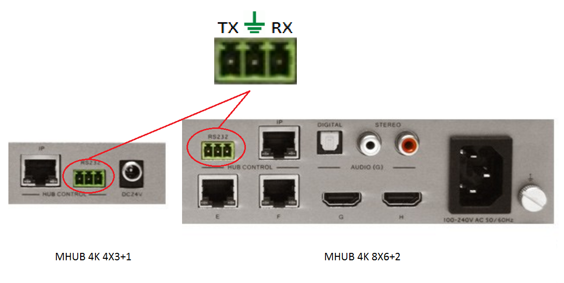

If you wish to control your MHUB 4K 4×3+1/8×6+2 from an external control system via a RS232 connection you will need to wire the included phoenix connector to the following specification.
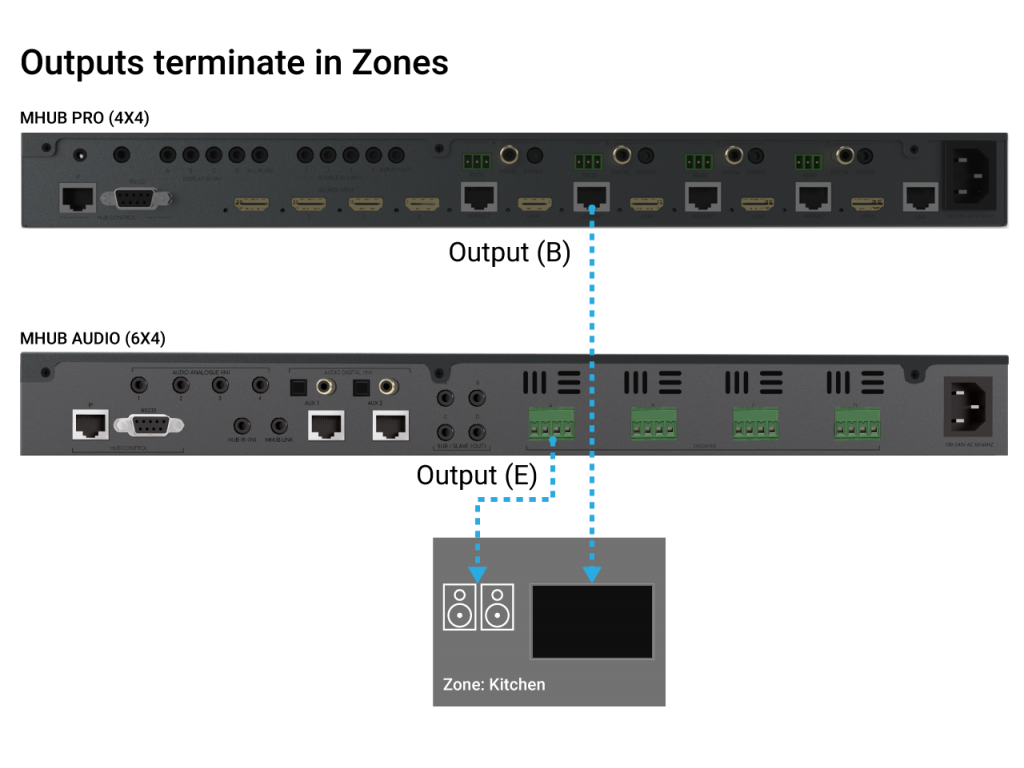
Zones define a physical space in a property where outputs from MHUB terminate.
A Zone can include a maximum of 1 video output and a maximum of 4 audio outputs. For example, you can create a zone called “Kitchen” and assign 1 video and 1 audio output to it to provide you with viewable TV and sound. A Zone must contain at least 1 output from an MHUB for it to be addressable for control. Note: outputs can not be shared or split to more than 1 Zone.
If your MHUB is marked with “TPC” then it is capable of passing a HDR picture to your display. There are a number of reasons why HDR may not be fed through your HDA device. This support post aims to troubleshoot the most common reasons and how to resolve them.
Important: there are different versions of HDR, make sure your display supports the format your source is outputting!
There are multiple variants of HDR such as HLG, HDR10+ and Dolby Vision, please ensure your display supports the relevant HDR technology.
When connecting your HDR enabled source and display to a HDA system you may need to adjust some settings to get it to work.
Modular units have the ability to receive Infra-red(IR) commands in two different ways; Code-based IR and Contextual based IR. Code-based IR uses unique codes for each room/output, whilst Contextual IR uses a single set of codes, with the unit determining where the IR command originated.
If you wish to revert the unit to Code based IR control please edit the settings.ini file on the SD card (Please use only PC based systems to edit the SD card contents) and remove the following information.
cir1 = 0x00ff9867
cir2 = 0x00ffd827
cir3 = 0x00ff8877
cir4 = 0x00ffa857
cir1 = 0x00ff807f
cir2 = 0x00ff00ff
cir3 = 0x00ff30cf
cir4 = 0x00ff906f
HDanywhere 2K systems, such as the mHub 2K family, require a single network cable to be run from each HDTV location, back to a central point.
HDanywhere 2K systems use HDMI over Cat technology to transmit over a single Cat5e/6/7 cable up to a 50 metre distance.
IR codes for MHUB systems (not Modular or Multiroom+) including power control available here:
| Error Code | Description |
| 1001 | Corrupt Service Card – Replace the SDCard or format and re-create |
| 1002 | Insert valid SDCard – No card detected or installed in the unit |
| 1003 | Write Protect Mode – SDCard is in write protect mode |
| 1004 | System Failure – MatrixOS is missing from the system and needs to be installed – i.e. rebuild the SDCard |
| 1005 | Insert Service Card – Insert an SDCard with a valid matrix OS firmware image |
| 1006 | Update failed – No firmware image found |
| 1007 | Update failed – Firmware image is corrupt or invalid |
| 1008 | Update failed – Firmware image is too large for the system. |
| 1009 | Remove service card – A bulk update card is installed and the update is complete, ready for a normal service card. |
| 1010 | Onscreen message varies – The unit update has failed and will be showing where internally in the unit it has failed. |
| 1011 | Update failed writing to flash. A critical error and process was stopped |
| 1012 | Communication Fault – The system cannot bring up internal communication bus and is unable to proceed |
| 1013 | Module Fault – Comes with specified module number |
| 1014 | System Fault – An internal IC has failed, indicated by the extended error code |
| 1015 | Input hotplug fault. Unable to enable the hot plug 5V voltage for one or more input modules |
| 1016 | EDID Setup Fault – The system cannot bring up the EDID mixing routines |
| 1017 | Communication fault – The system cannot bring up the 5V I2C communication line |
| 1018 | IR Mux fault – The system cannot bring up the IR Mux subsystem |
| 1019 | IR Capture fault – The system cannot bring up the IR capture subsystem |
| 1020 | Local Network Failure – Unable to ping the local gateway |
| 1021 | Remote Net Failure – Unable to ping DNS servers |
| 1022 | Module Power Fault – The system reports that one of the voltages used to power modules is not functioning correctly |
| 1023 | Network HW Fault – The network hardware has a hardware fault |
| 1024 | Network HW Fault – EDID Read Failure – the system has failed to read the EDID from a connected device |
| 1025 | Network HW Fault – Filesystem Fault – The system has an issue reading from the SDCard |
| 1026 | Network HW Fault – Invalid update URL – The custom URL for retrieving updates is not valid |
| 1027 | Network HW Fault – Discovery failure – the system has failed to enable its auto discovery feature (SDDP) |
| 1028 | Network HW Fault – Invalid Aux MCU – the Component fitted is incorrect |
| 1029 | Update failed – This version is too old for this part |
| 1030 | Invalid Module – A module is inserted in the wrong port |