HDANYWHERE will be operating a reduced customer and dispatch service over Christmas and New Year. Dispatch will resume in the new year and the last day for dispatch is Thursday 21st. During this period a reduced customer service level will operate meaning Call Back Requests and WhatsApp messages will be temporarily disabled until January 2nd.
Thursday 21st December 2023: Last day of dispatch
Friday 22nd December 2023: No dispatch. Reduced customer service.
Wednesday 27th December 2023: No dispatch. Reduced customer service.
Thursday 28th December 2023: No dispatch. Reduced customer service.
Friday 29th December 2023: No dispatch. Reduced customer service.
Tuesday 2nd January 2024: Dispatch resumes. Full customer service.
This guide will show you how to build a stacked system using an MHUB (4×4)/(6×6) 100A and an MZMA (6×4) 55 with uControl acting as the main method of control for the system.
Make sure the only HDA devices on the network are the ones you want to put into the Stacked System. If you still cannot discover them in the app consider your network infrastructure, the app may struggle to find the system(s) if there are things like network switches in the residence, so try simplifying it whilst going through setup.
This guide is intermediate in difficulty and assumes that you have installed MHUB before in standalone mode.
It is strongly recommended that you read this guide carefully before commissioning your stacked system to ensure all features of the system work as expected.
the following terms are used throughout this guide.
Foundation Layer
The MHUB system which is directly connected to a video source(s) is referred to as the Foundation Layer. Ideally, this system should be physically installed at the bottom of your MHUB stack. Inside uOS this system is referred to as S1 (see Stack Layer below).
Connections
A Connection is used to define the cabled connections between each component in an MHUB/MZMA Stack. The combination of HDA devices in your Stack will determine which ports can be paired or not.
Stack Layer
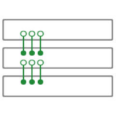
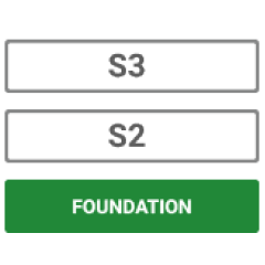
The Stack Layer is an alphanumeric identifier within uOS, starting from the Foundation Layer (Layer S1). This identifier represents the order of HDA systems that are connected to one another by a Connection. For example, if you had four HDA systems stacked together, then you would start with the Foundation Layer (Layer S1), then the second HDA device (Layer S2), followed by the third HDA device (Layer S3) and, finally, the fourth HDA device (Layer S4).
Master / Controller
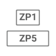
An HDA device (like a Zone Processor) designed to control MHUB and/or MZMA (6×4) 55 systems operating in Stack mode. Any Stack that needs to be controlled by uControl must have a Master / Controller present in your setup. This is identified as M1 in uOS.
uControl
uControl is our control system for configuration and control of stacked systems. When we refer to “uControl” in this article we are referring to our app specifically.
Wiring
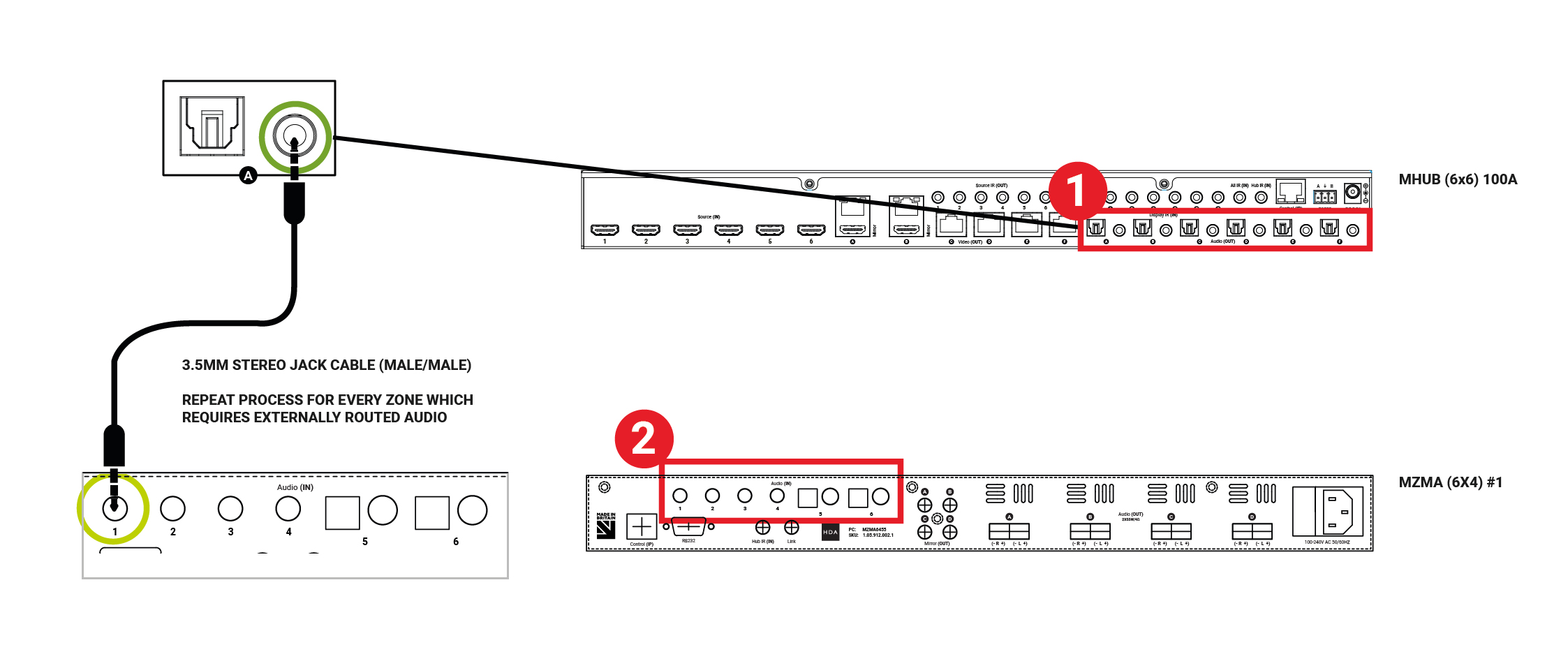
A video and audio system is made possible by the audio ports on the back of the MHUB (4×4)/(6×6) 100A and MZMA (6×4) 55. Connect the 3.5mm Stereo port labelled Audio (In) on the back of the MZMA (6×4) 55 to the 3.5mm Stereo port on the back of the MHUB (4×4)/(6×6) 100A labelled Audio (Out).
“Audio (OUT)”
The audio ports on the back of the MHUB (4×4)/(6×6) 100A are labelled Audio (Out).
“Audio (In)”
The audio ports on the back of the MZMA (6×4) 55 are labelled Audio (In).
Figure 1: Showing stereo connection between MHUB (4×4)/(6×6) 100A and MZMA (6×4) 55.
Connect your 3.5mm stereo cables to the Audio (In) port of the MZMA (6×4) 55 and repeat for every zone.
Connect your 3.5mm stereo cables to the Audio (Out) port of the MHUB (4×4)/(6×6) 100A and repeat for every zone.
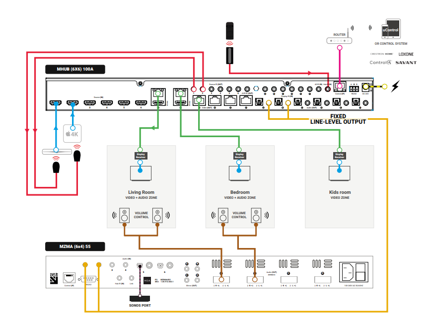
Connect speakers via phoenix connector into the Audio (OUT) of the MZMA (6×4) 55 and repeat for every zone.
Connect your HDBaseT/network cabling into the Video (OUT) of your MHUB (4×4)/(6×6) 100A then into your display receiver and repeat for each zone.
Figure 2: Wiring guide showing video and audio connection between MHUB (4×4)/(6×6) 100A and MZMA (6×4) 55(s).
Watch video: How to wire MHUB (4×4)/(6×6) 100A and MZMA (6×4) 55 stack
This video describes how to wire an MHUB (4×4)/(6×6) 100A with an MZMA (6×4) 55 to create a stack.
Initialising your Stacked Video and Audio System using uControl
Ensure that your MHUB (4×4)/(6×6) 100A and MZMA (6×4) 55 are correctly wired for stacking covered in the part above and that the following is completed:
Both MHUB (4×4)/(6×6) 100A and MZMA (6×4) 55 systems in your stack are powered ON.
Your Master / Controller device (Zone Processor or uControl Connect) is powered ON.
All HDA systems and the Master Controller are connected to the LAN and reachable by their IP address.
IMPORTANT: All hardware has been individually updated to the latest software version.
Configuring MHUB (4×4)/(6×6) 100A and MZMA (6×4) 55 to operate in stacked mode cannot be undone without resetting the system and starting again. Ensure that you have your wiring information handy and that you know exactly how the system is connected together before initialising your stack.
1. Connect to system
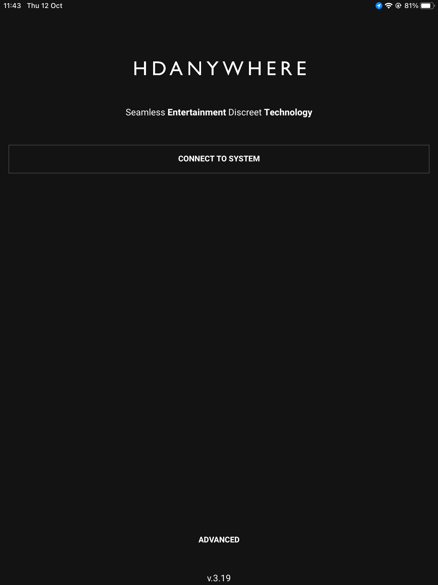
To get started press connect to system on the uControl Homepage.
Connect to system
2. Stack
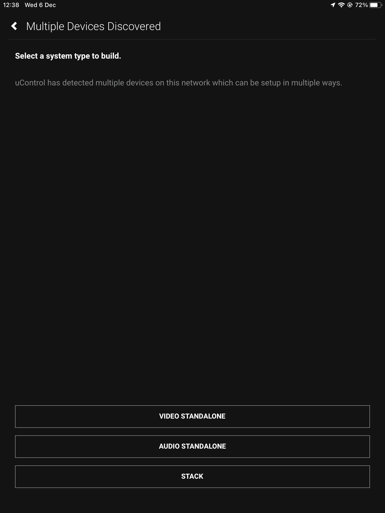
If the HDA devices are on the network you will be presented with the option to create a stack, video standalone or audio standalone, as this contains an MHUB (4×4)/(6×6) 100A and an MZMA (6×4) 55 choose stack.
Connect to system
Stack
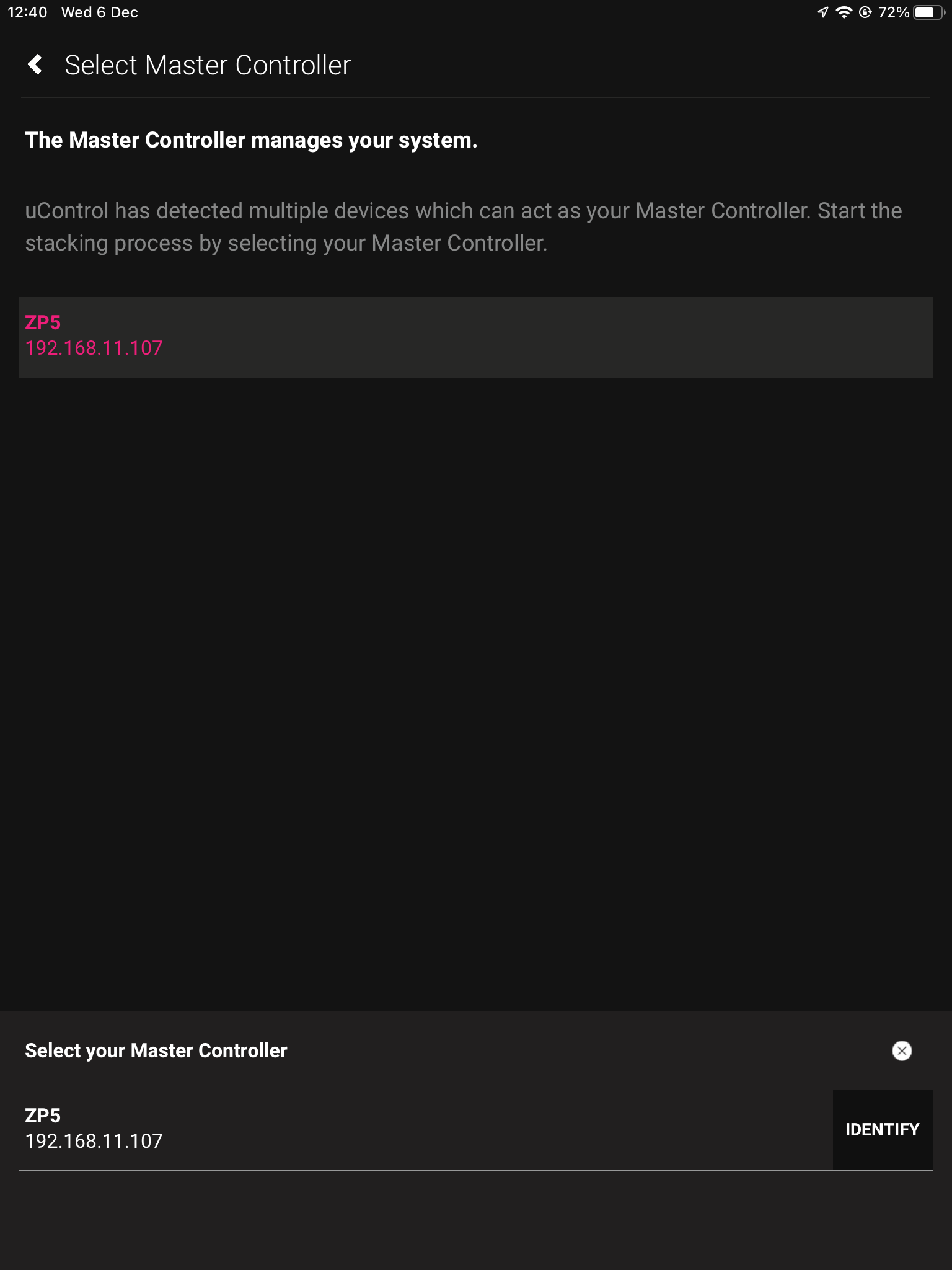
3. Master Controller
The Zone Processor acts as the bridge between 2 or more HDA devices and all data goes through this device, acting as a brain. It needs to be selected as the Master Controller.
Connect to system
Stack
Master Controller
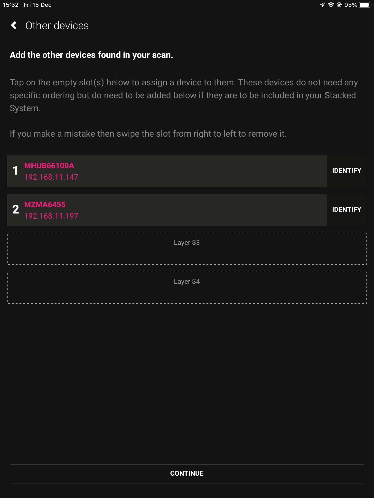
4. Layers
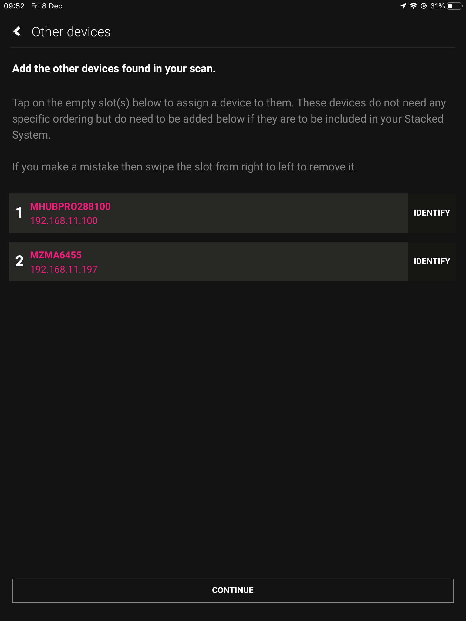
Next we need to choose our layers, starting with the Foundation Layer. Press identify to the right of the HDA device to make the power LED blink, when you know which is which select your primary MHUB for 1 and the other HDA device for 2, then hit continue.
Connect to system
Stack
Master Controller
Layers
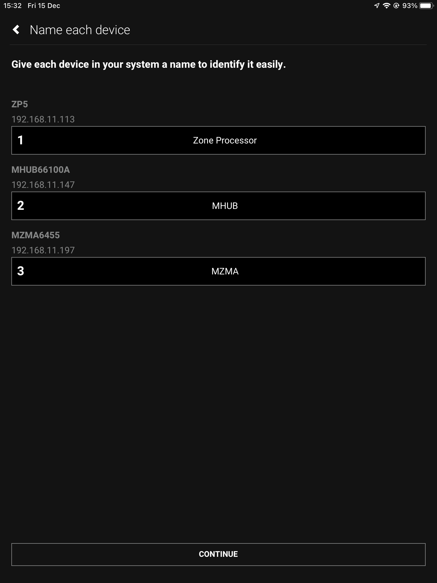
5. Naming devices
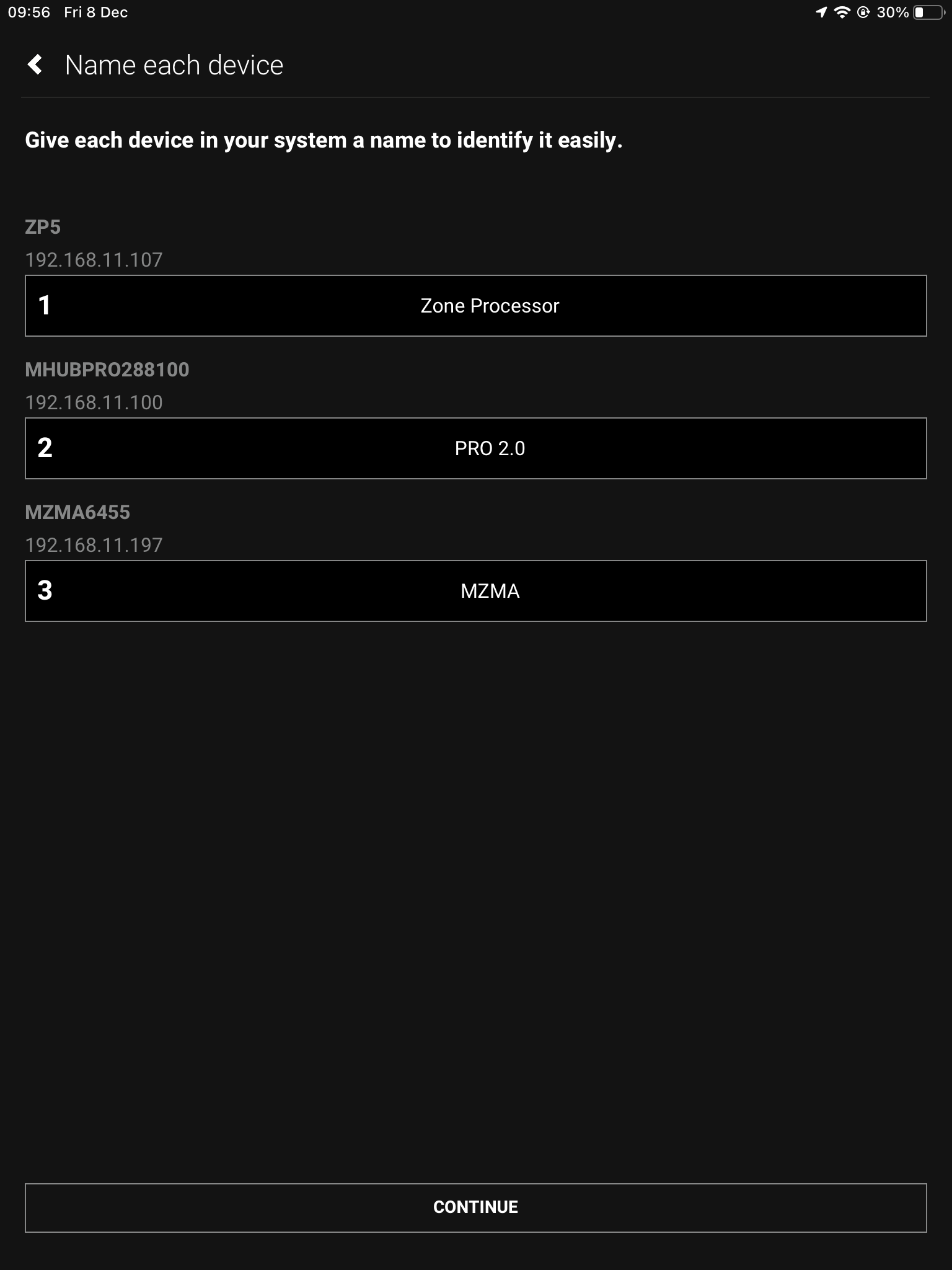
Now we have chosen where our devices go in the stack, we must name them so that they’re easily identifiable.
Connect to system
Stack
Master Controller
Layers
Naming
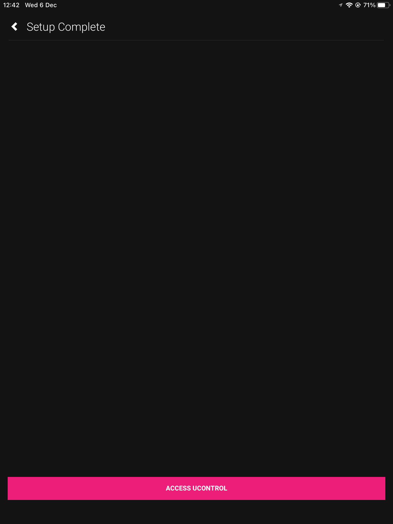
6. Access uControl
Assigning our hardware has now been complete, after pressing access uControl we will continue the setup in uOS.
Connect to system
Stack
Master Controller
Layers
Naming
Access uControl
7. Cloud Account
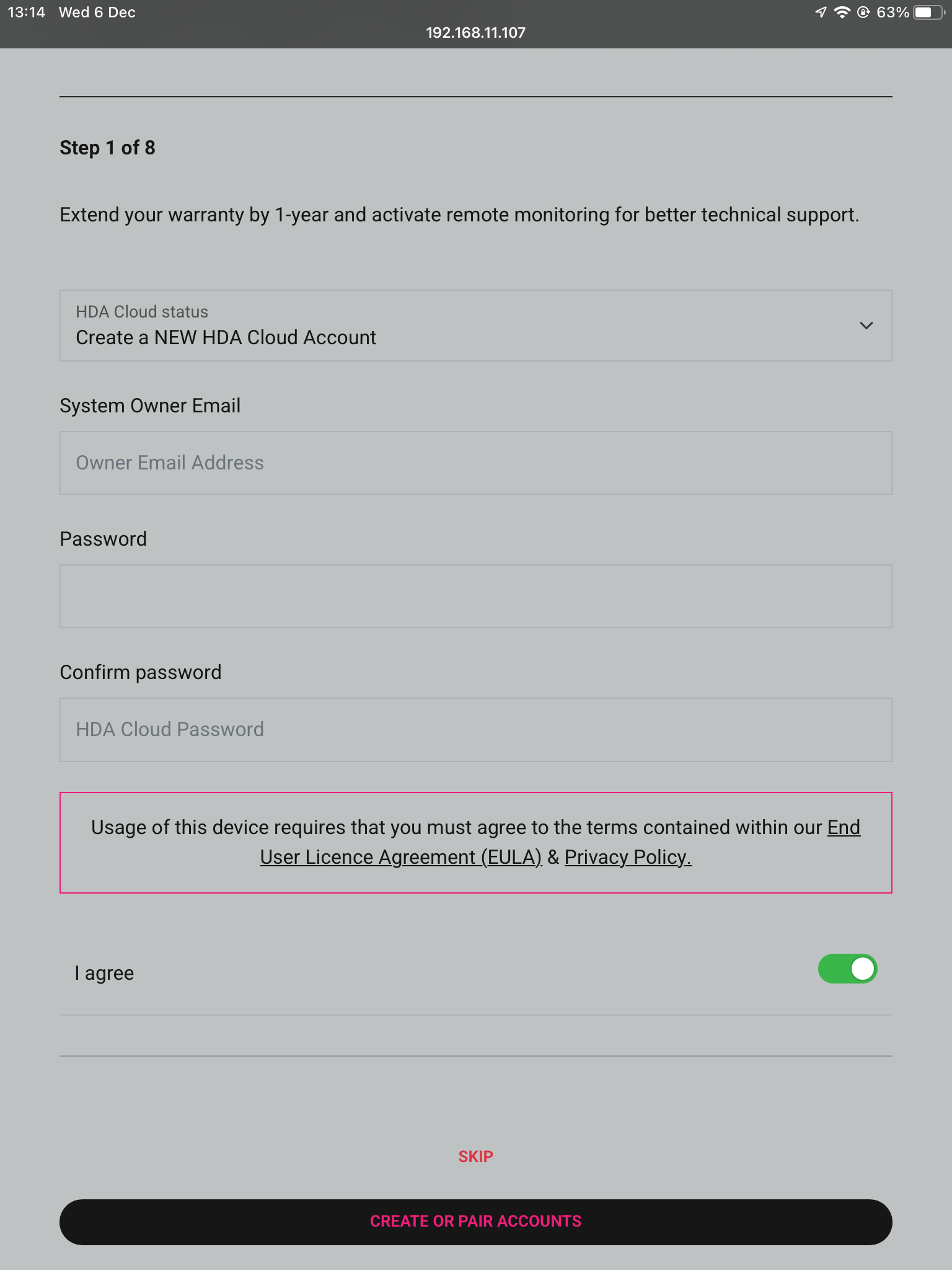
The first thing to do in uOS is to create a Cloud Account, or pair it to an existing one if possible. Cloud Accounts allow for Installers and HDA Tech Support to gather additional information regarding your systems performance.
Connect to system
Stack
Master Controller
Layers
Naming
Access uControl
Cloud Account
8. Control Type
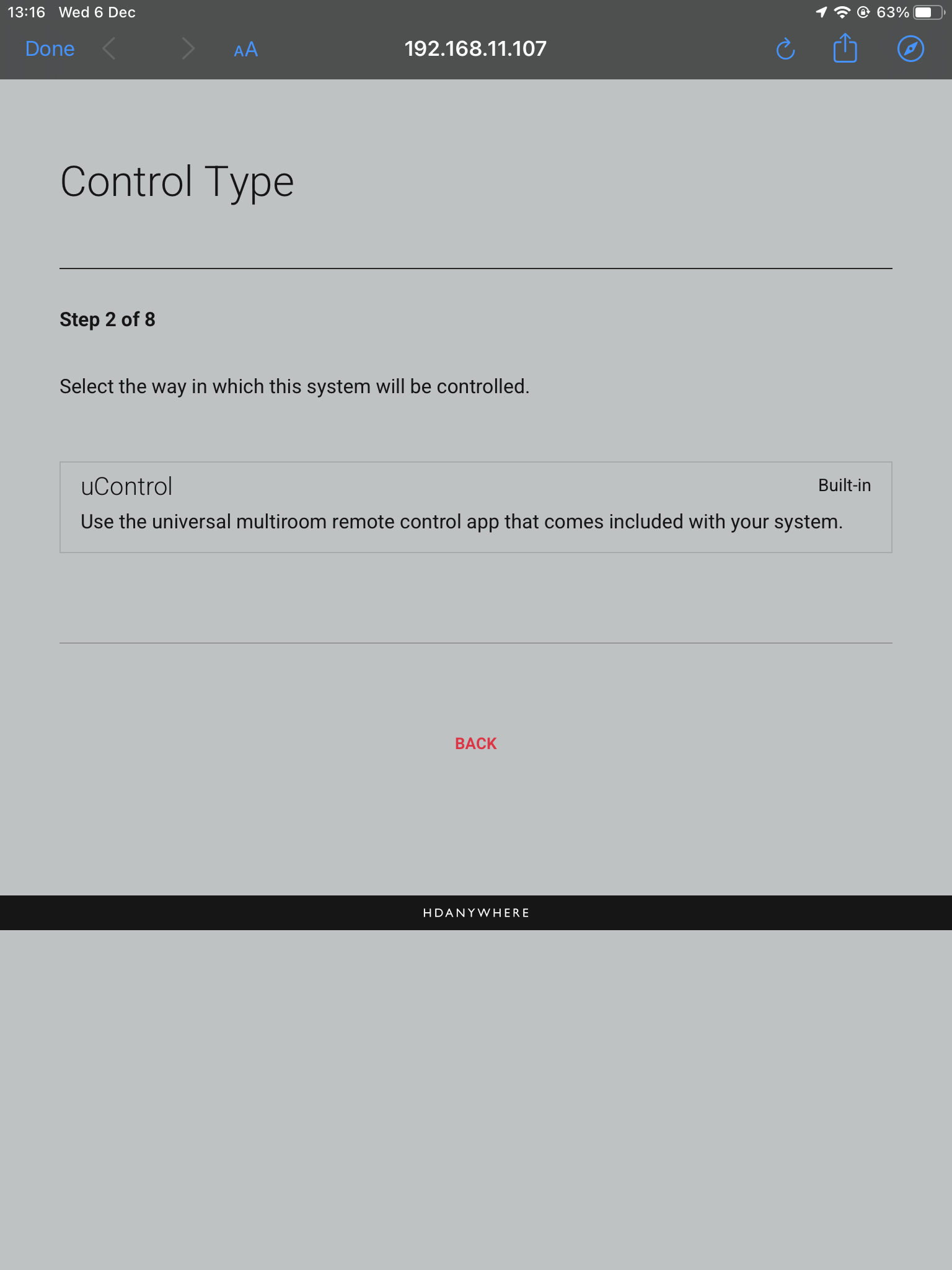
Choose uControl as Control Tyoe.
Connect to system
Stack
Master Controller
Layers
Naming
Access uControl
Cloud Account
Control Type
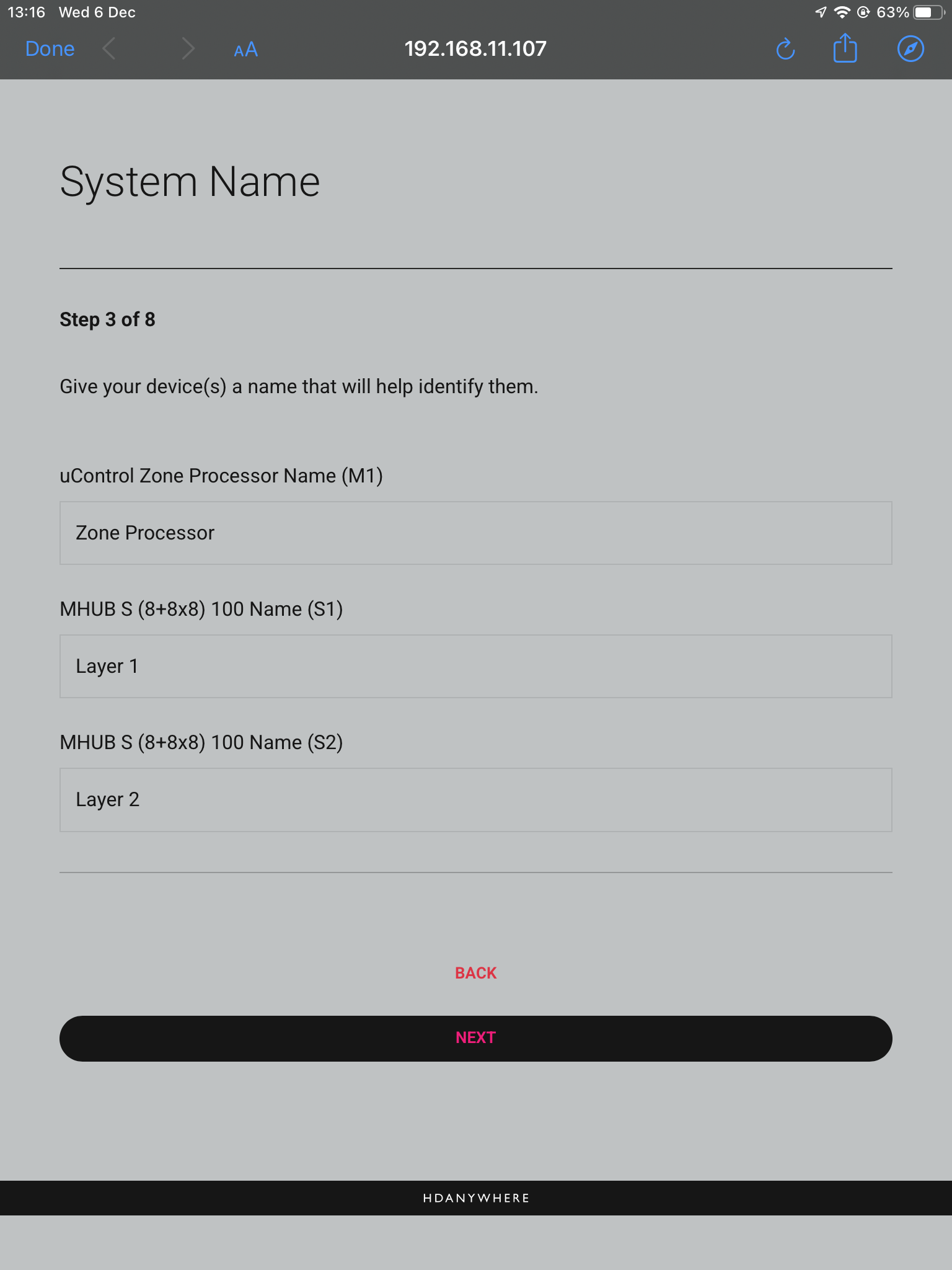
9. System Name
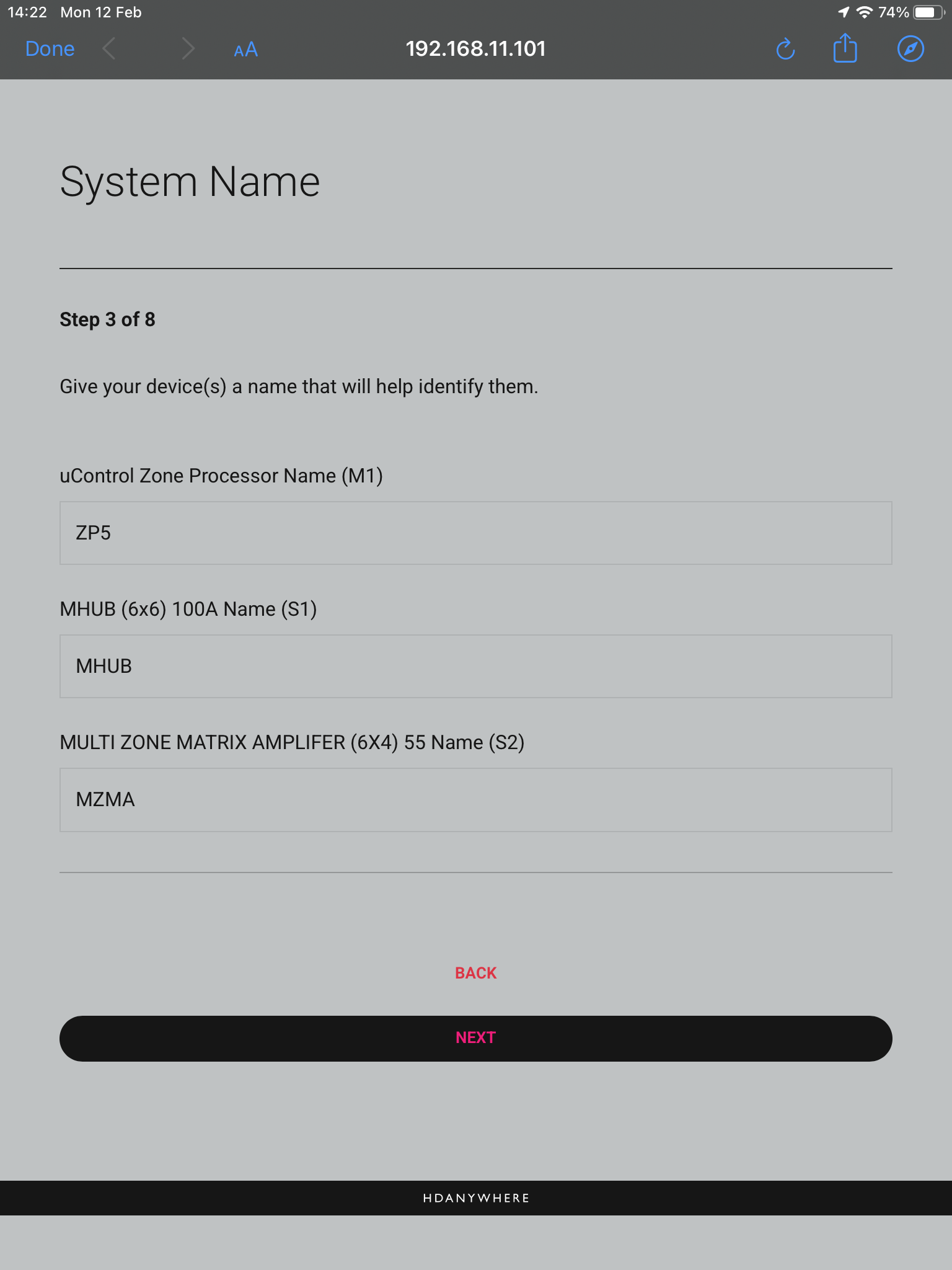
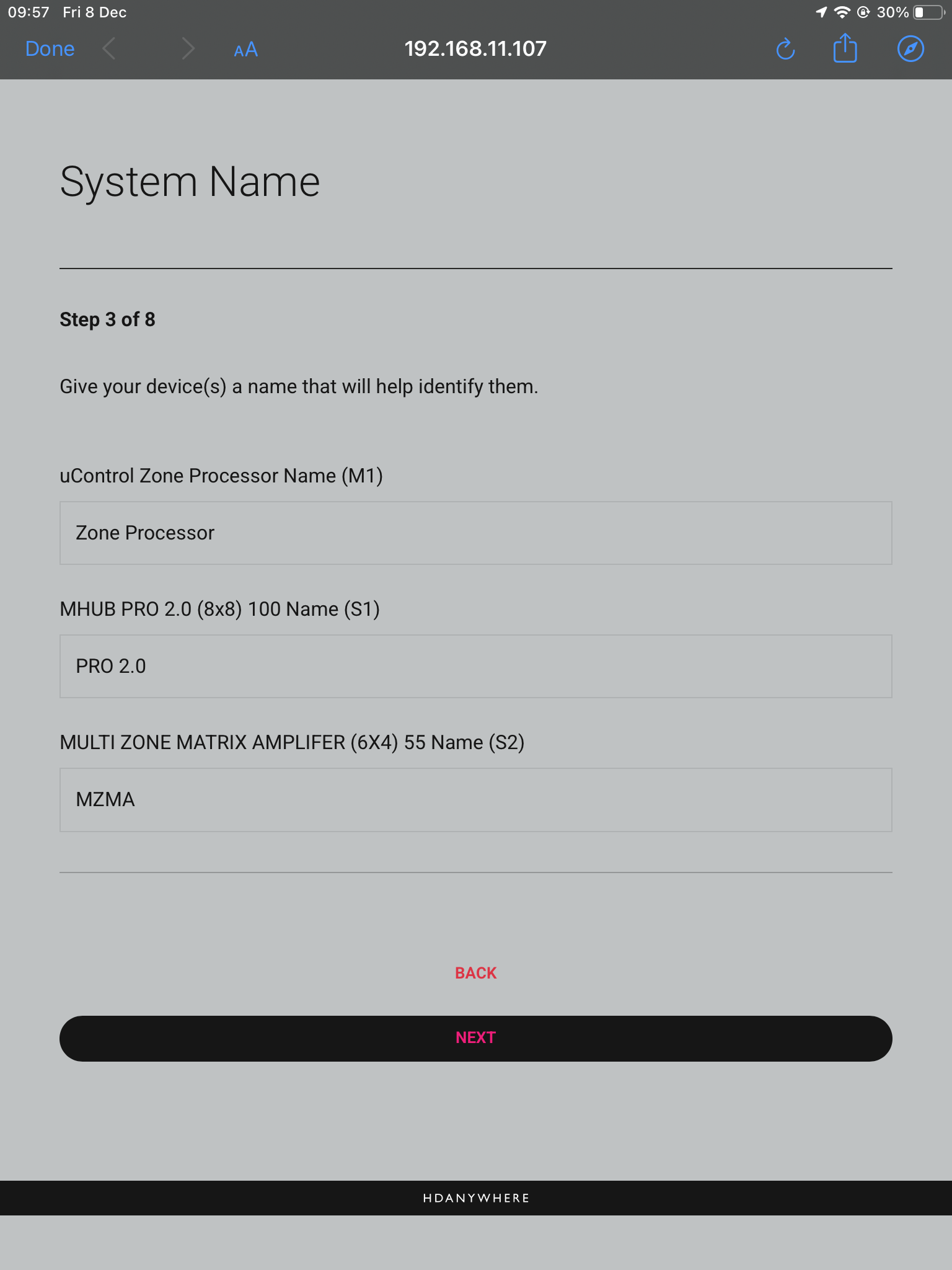
Confirm the names of your devices.
Connect to system
Stack
Master Controller
Layers
Naming
Access uControl
Cloud Account
Control Type
System Name
10. Setup Connections
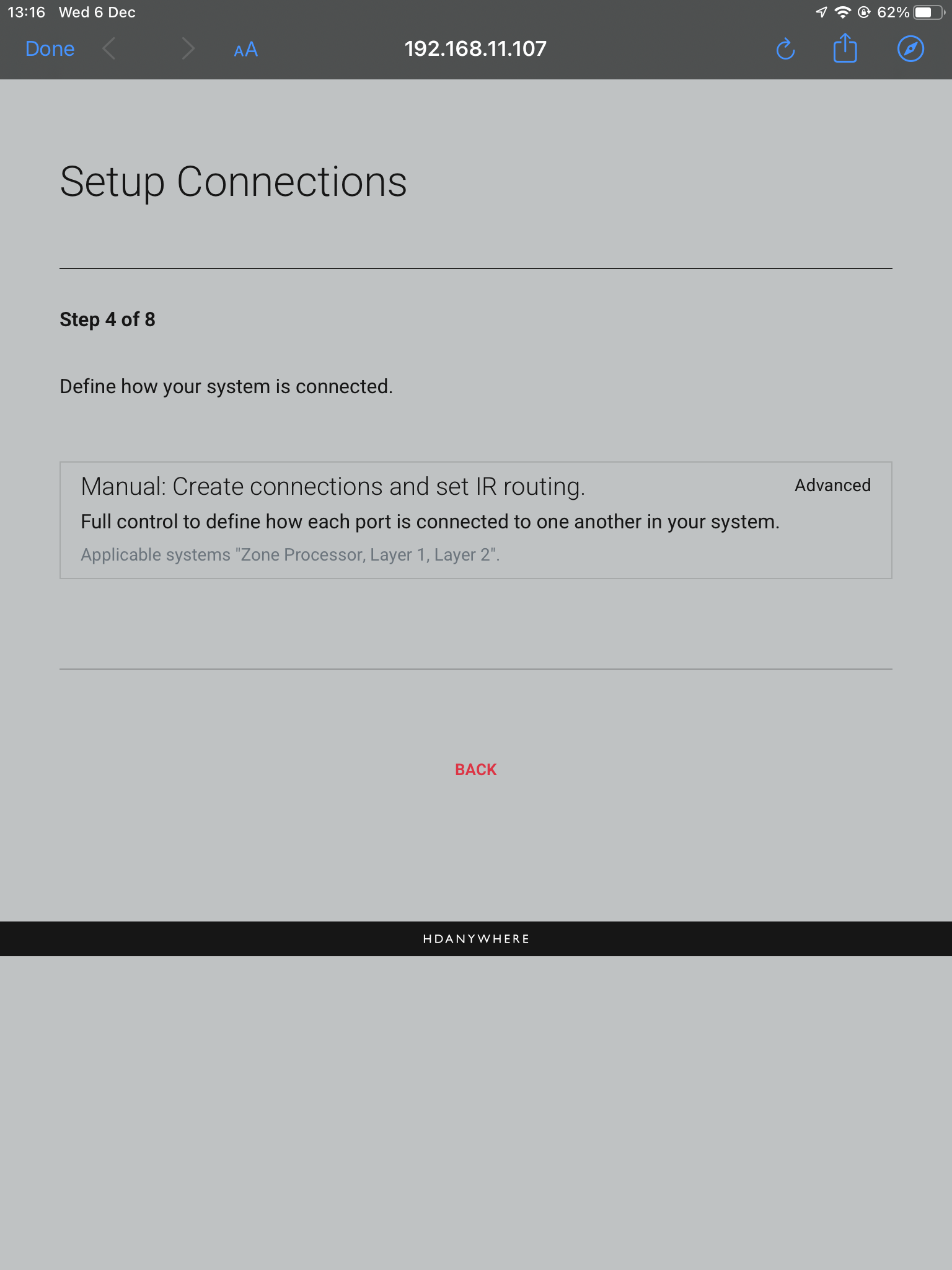
This next step will allow us to make the manual connections between the multiple devices.
Connect to system
Stack
Master Controller
Layers
Naming
Access uControl
Cloud Account
Control Type
System Name
Connections
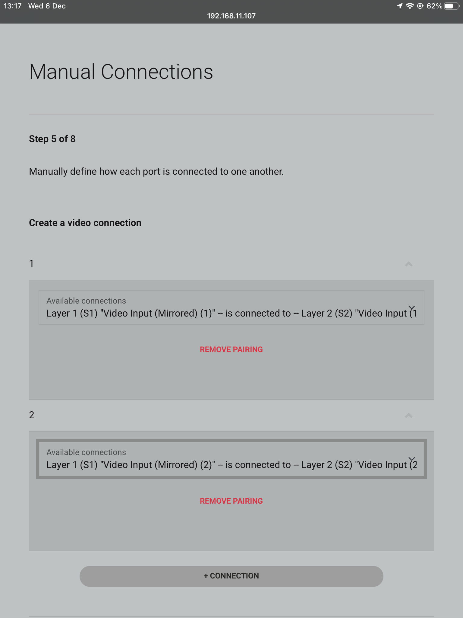
11. Manual Connections
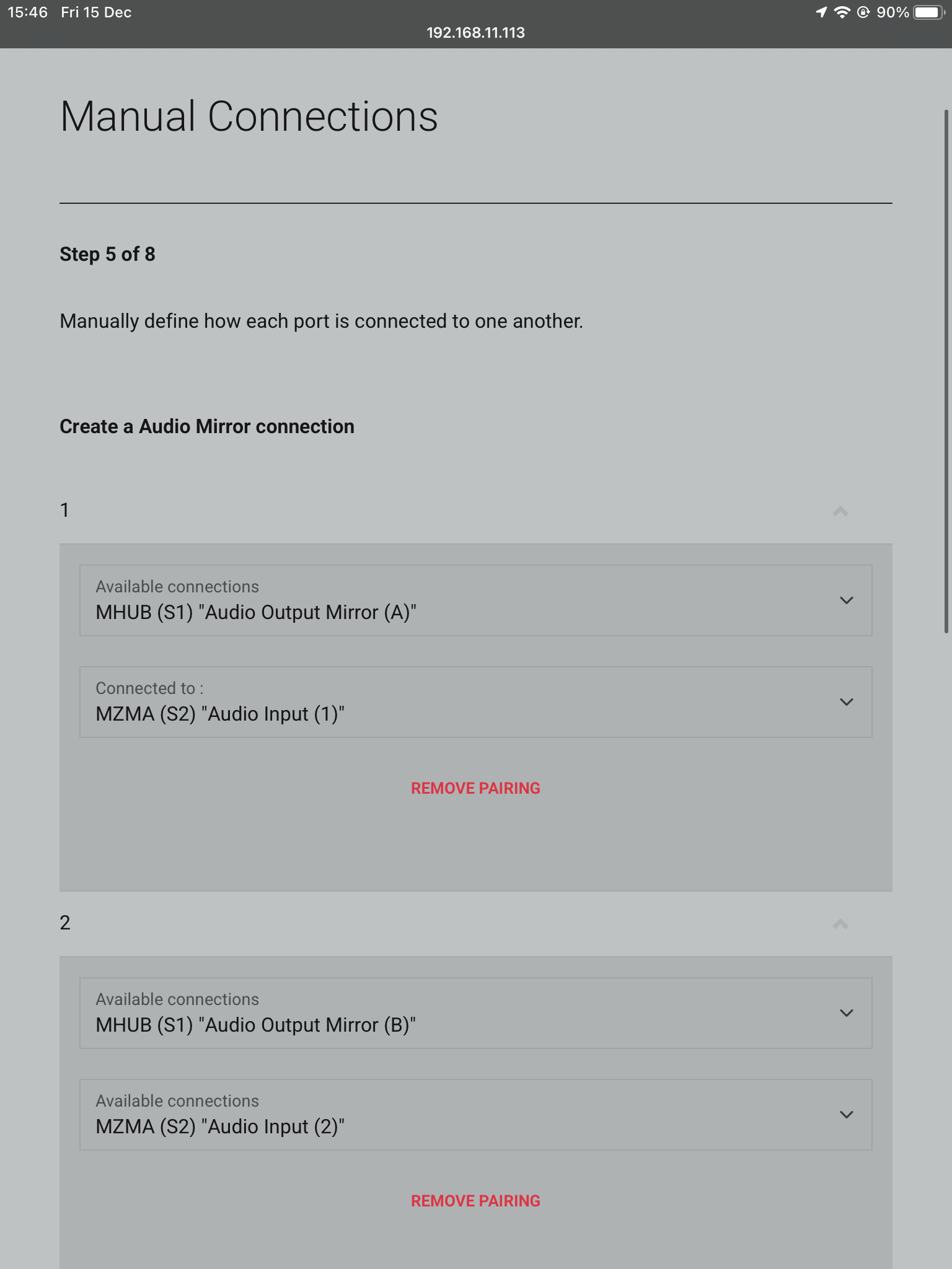
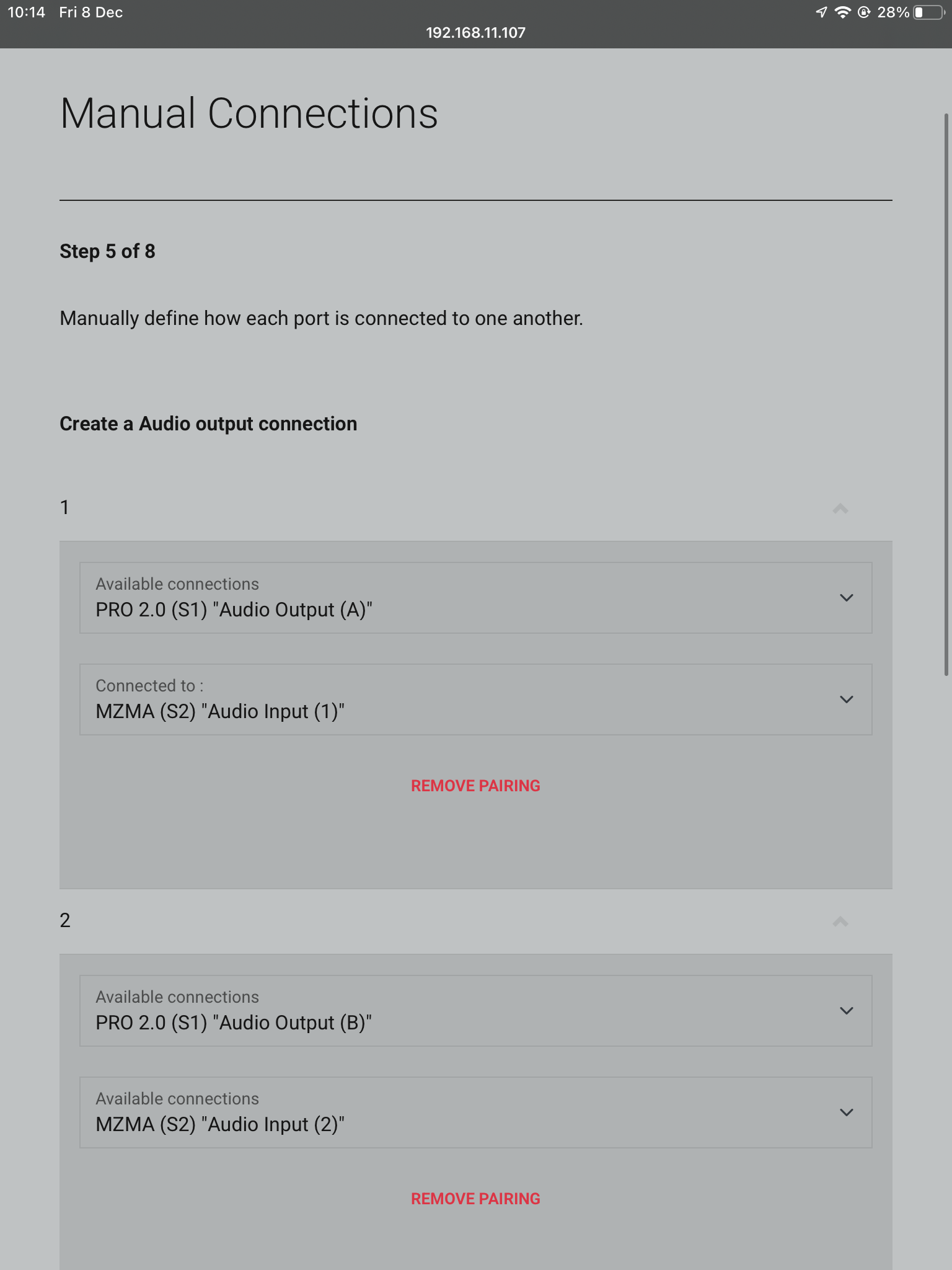
This is where you tell the system how it is all linked. In this example Audio Output (A) is connected to Audio Input (1). For the second connection Audio Output (B) is connected to Audio Input (2). Repeat this step for every required connection.
Connect to system
Stack
Master Controller
Layers
Naming
Access uControl
Cloud Account
Control Type
System Name
Connections
Manual Connections
12. Naming Sources
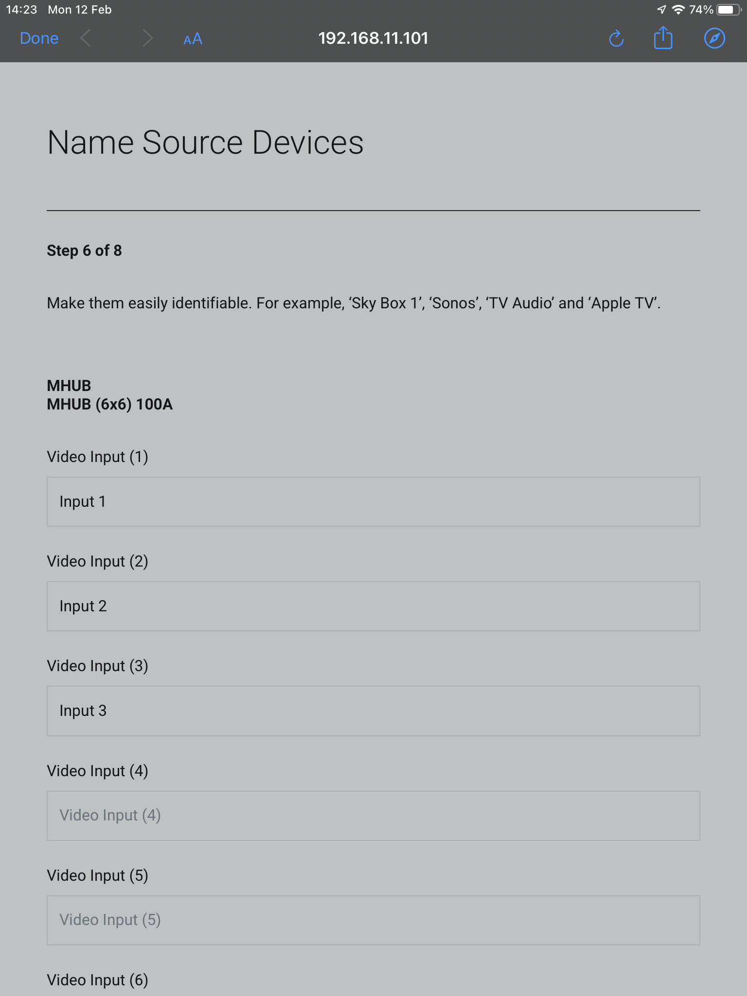
Name your inputs after what identifies them the easiest. This can be naming it after the specific source that is connected, or naming them incrementally.
Connect to system
Stack
Master Controller
Layers
Naming
Access uControl
Cloud Account
Control Type
System Name
Connections
Manual Connections
Sources
13. Zones
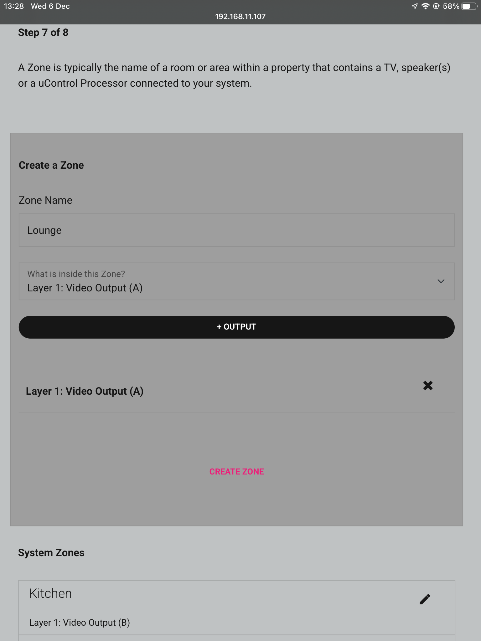
A zone is where a display is located, so name the zones after the room those displays are in. To add an output to a zone, choose which output from the list and then press “+OUTPUT”, check that the output has been added below in bold and then press “Create Zone”. Repeat process for all zones.
Connect to system
Stack
Master Controller
Layers
Naming
Access uControl
Cloud Account
Control Type
System Name
Connection
Manual Connections
Sources
Zones
14. Complete
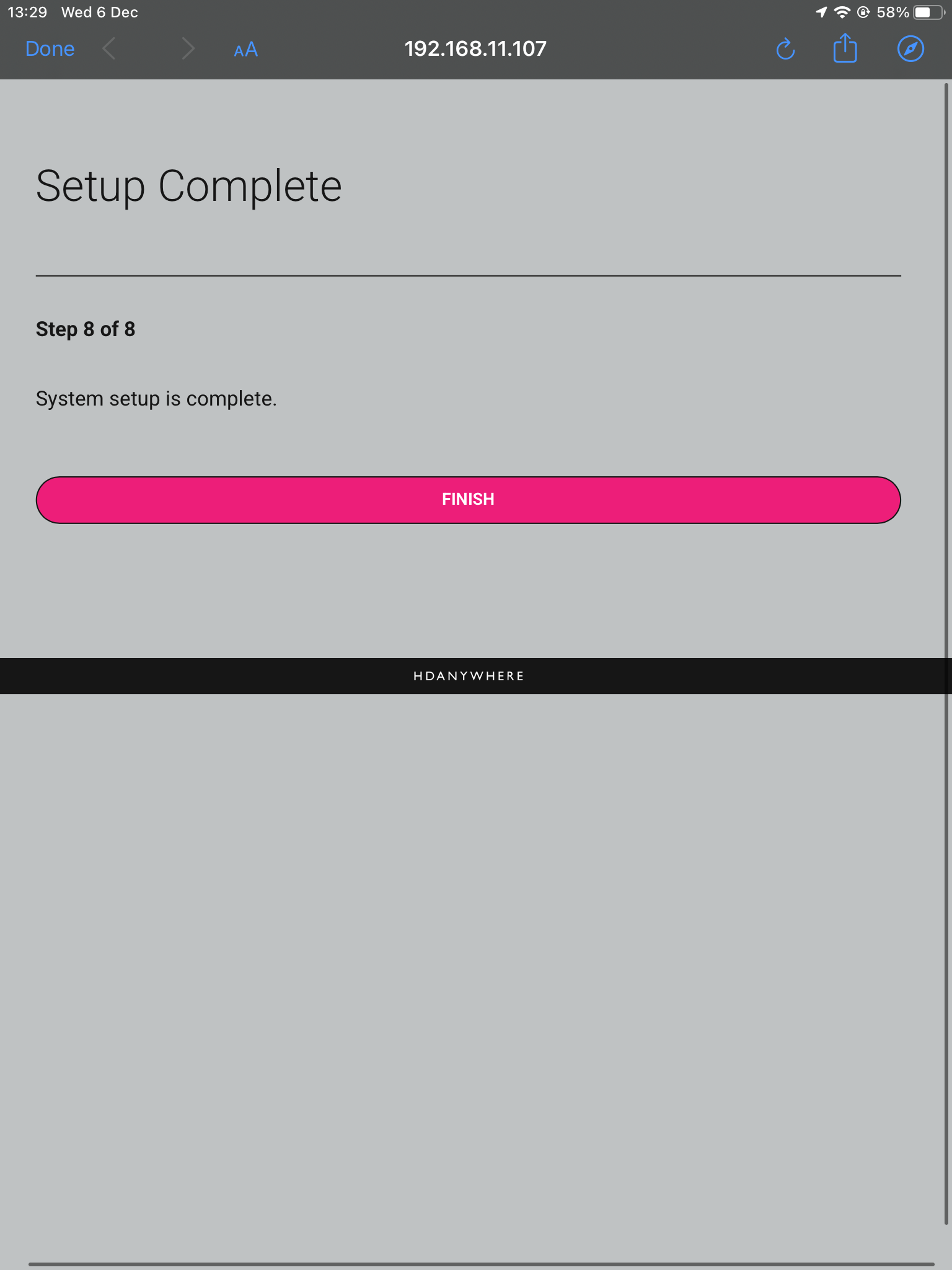
Now the system has been configured press “Finish” and you will be taken out of the web interface.
Connect to system
Stack
Master Controller
Layers
Naming
Access uControl
Cloud Account
Control Type
System Name
Connection
Manual Connections
Sources
Zones
Complete
15. Reboot
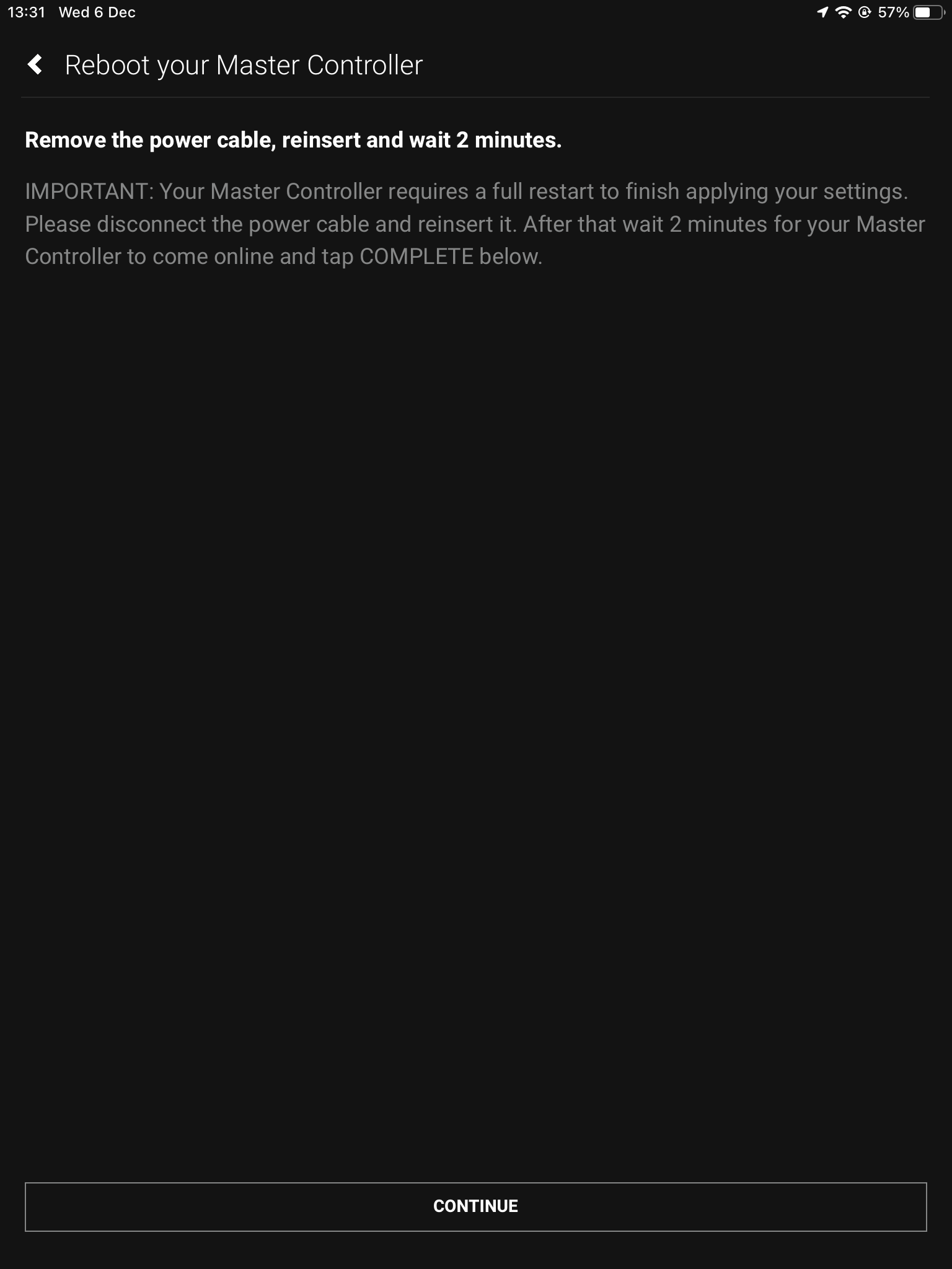
The last step is to remove the power cable from your Zone Processor and wait 2 minutes, then plug it back in. Ths is needed to apply the settings you have just changed, once the 2 minutes is up press “Continue”.
Connect to system
Stack
Master Controller
Layers
Naming
Access uControl
Cloud Account
Control Type
System Name
Define Connection
Manual Connections
Sources
Zones
Complete
Reboot
After hitting continue you will be taken into the uControl interface where you can begin setting up the necessary packs and additional features like Functions and Sequences. For more guides on setting up systems after the first boot, please refer to our uOS support page.
This guide will show you how to build a stacked system using an MHUB PRO 2.0 and an MZMA (6×4) 55 with uControl acting as the main method of control for the system.
Make sure the only HDA devices on the network are the ones you want to put into the Stacked System. If you still cannot discover them in the app consider your network infrastructure, the app may struggle to find the system(s) if there are things like network switches in the residence, so try simplifying it whilst going through setup.
This guide is intermediate in difficulty and assumes that you have installed MHUB before in standalone mode.
It is strongly recommended that you read this guide carefully before commissioning your stacked system to ensure all features of the system work as expected.
the following terms are used throughout this guide.
Foundation Layer
The MHUB system which is directly connected to a video source(s) is referred to as the Foundation Layer. Ideally, this system should be physically installed at the bottom of your MHUB stack. Inside uOS this system is referred to as S1 (see Stack Layer below).
Connections
A Connection is used to define the cabled connections between each component in an MHUB/MZMA Stack. The combination of HDA devices in your Stack will determine which ports can be paired or not.
Stack Layer
The Stack Layer is an alphanumeric identifier within uOS, starting from the Foundation Layer (Layer S1). This identifier represents the order of HDA systems that are connected to one another by a Connection. For example, if you had four HDA systems stacked together, then you would start with the Foundation Layer (Layer S1), then the second HDA device (Layer S2), followed by the third HDA device (Layer S3) and, finally, the fourth HDA device (Layer S4).
Master / Controller
An HDA device (like a Zone Processor) designed to control MHUB and/or MZMA (6×4) 55 systems operating in Stack mode. Any Stack that needs to be controlled by uControl must have a Master / Controller present in your setup. This is identified as M1 in uOS.
uControl
uControl is our control system for configuration and control of stacked systems. When we refer to “uControl” in this article we are referring to our app specifically.
Wiring
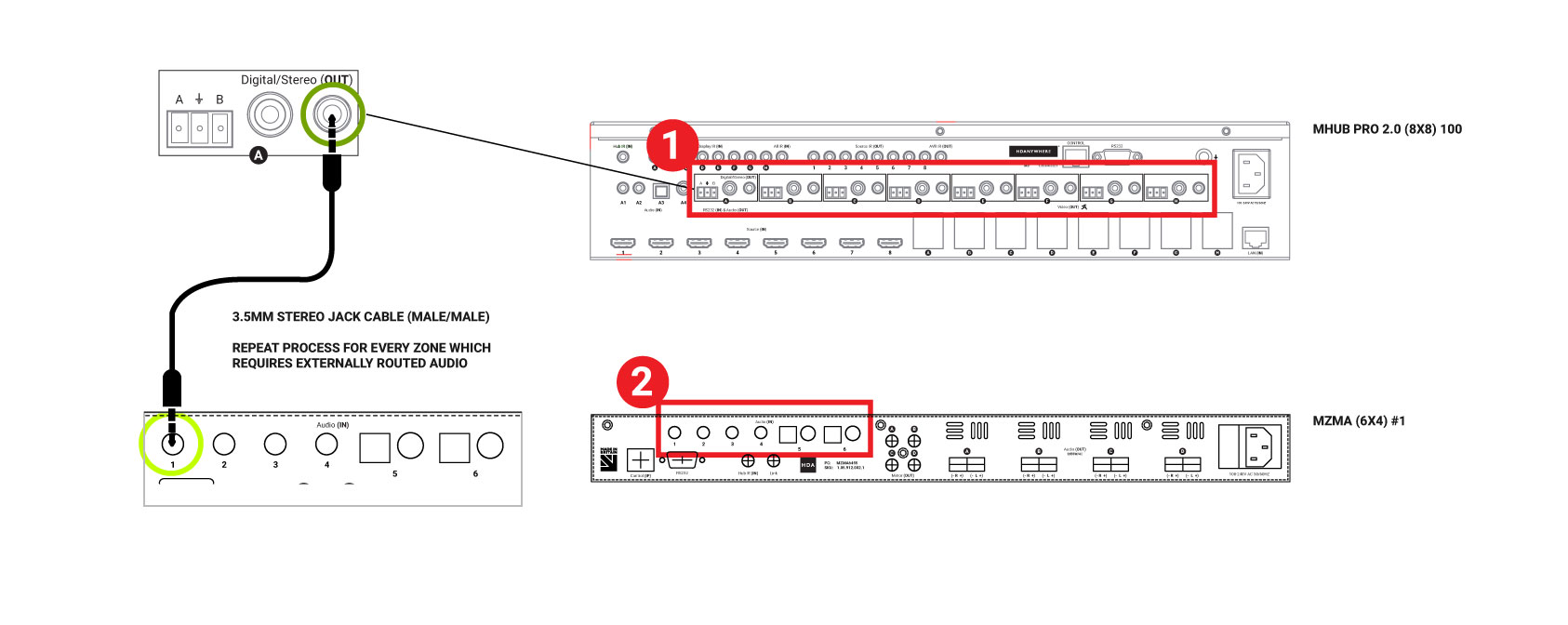
A video and audio system is made possible by the audio ports on the back of the MHUB PRO 2.0 and MZMA (6×4) 55. Connect the 3.5mm Stereo port labelled Audio (In) on the back of the MZMA (6×4) 55 to the 3.5mm Stereo port on the back of the MHUB PRO 2.0 labelled Audio (Out).
“Audio (Out)”
The audio ports on the back of the MHUB PRO 2.0 are labelled Audio (Out).
“Audio (In)”
The audio ports on the back of the MZMA (6×4) 55 are labelled Audio (In).
Figure 1: Showing stereo connection between MHUB PRO 2.0 and MZMA (6×4) 55.
Connect your 3.5mm stereo cables to the Audio (In) port of the MZMA (6×4) 55 and repeat for every zone.
Connect your 3.5mm stereo cables to the Audio (Out) port of the MHUB PRO 2.0 and repeat for every zone.
Connect speakers via phoenix connector into the Audio (OUT) of the MZMA (6×4) 55 and repeat for every zone.
Connect your HDBaseT/network cabling into the Video (OUT) of your MHUB PRO 2.0 then into your display receiver and repeat for each zone.
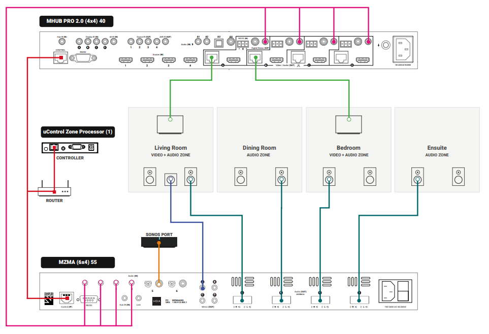
Figure 2: Wiring guide showing video and audio connection between MHUB PRO 2.0 and MZMA (6×4) 55(s).
Watch video: How to wire MHUB PRO 2.0 and MZMA (6×4) 55 stack
This video describes how to wire an MHUB PRO 2.0 with an MZMA (6×4) 55 to create a stack.
Initialising your Stacked Video and Audio System using uControl
Ensure that your MHUB PRO 2.0 and MZMA (6×4) 55 are correctly wired for stacking covered in the part above and that the following is completed:
Both MHUB PRO 2.0 and MZMA (6×4) 55 systems in your stack are powered ON.
Your Master / Controller device (Zone Processor or uControl Connect) is powered ON.
All HDA systems and the Master Controller are connected to the LAN and reachable by their IP address.
IMPORTANT: All hardware has been individually updated to the latest software version.
Configuring MHUB PRO 2.0 and MZMA (6×4) 55 to operate in stacked mode cannot be undone without resetting the system and starting again. Ensure that you have your wiring information handy and that you know exactly how the system is connected together before initialising your stack.
1. Connect to system
To get started press connect to system on the uControl Homepage.
Connect to system
2. Stack
If the HDA devices are on the network you will be presented with the option to create a STACK, VIDEO STANDALONE or AUDIO STANDALONE, choose STACK.
Connect to system
Stack
3. Master Controller
The Zone Processor acts as the bridge between 2 or more HDA devices and all data goes through this device, acting as a brain. It needs to be selected as the Master Controller.
Connect to system
Stack
Master Controller
4. Setting Stack Layers
Select your MHUB as the primary device, and then select MZMA as the secondary device.
Connect to system
Stack
Master Controller
Layers
5. Naming devices
Name the devices so that they’re easily identifiable.
Connect to system
Stack
Master Controller
Layers
Naming
6. Access uControl
Your HDA devices are now in Stack mode and are ready for configuration. You can now proceed to perform First Boot of your Stack with the Master Controller (M1)
Connect to system
Stack
Master Controller
Layers
Naming
Access uControl
7. Owner Account
Owner Accounts allow installers to add their HDA PRO account to their system for additional features, and to increase the warranty period. We recommend you do not skip this step.
Connect to system
Stack
Master Controller
Layers
Naming
Access uControl
Owner Account
8. Control Type
Choose uControl as the Control Type.
Connect to system
Stack
Master Controller
Layers
Naming
Access uControl
Owner Account
Control Type
9. System Name
Confirm the names of your devices.
Connect to system
Stack
Master Controller
Layers
Naming
Access uControl
Owner Account
Control Type
System Name
10. Setup Connections
This next step will allow us to make the manual connections between the multiple devices.
Connect to system
Stack
Master Controller
Layers
Naming
Access uControl
Owner Account
Control Type
System Name
Connections
11. Manual Connections
Connect your ports by linking Audio Input (1) to Audio Output (A), and the same for Audio Input (2) and Audio Output (B). Continue to do so until all your Audio Inputs are linked with your Audio Outputs. If you have 5 or more zones of audio requiring multiple MZMA’s, select MZMA (S3) from the drop down which will be your third HDA device in the stack as the MHUB PRO 2.0 is the primary, or (S1). Repeat the first steps until all Audio Inputs are assigned to Audio Outputs.
Connect to system
Stack
Master Controller
Layers
Naming
Access uControl
Owner Account
Control Type
System Name
Connection
Manual Connections
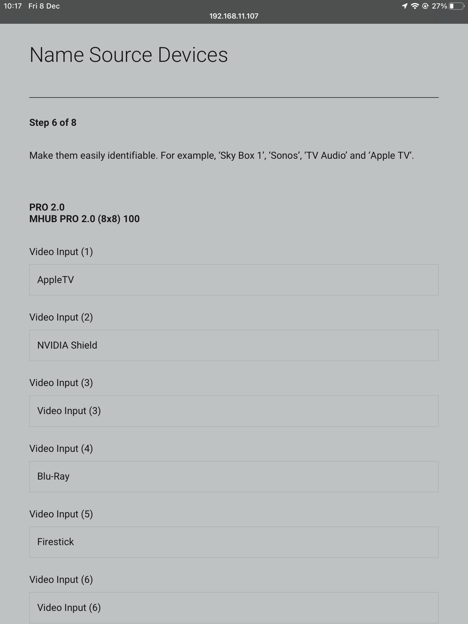
12. Naming Sources
Name your inputs after what identifies them the easiest. This can be naming it after the specific source that is connected, or naming them incrementally.
Connect to system
Stack
Master Controller
Layers
Naming
Access uControl
Owner Account
Control Type
System Name
Connection
Manual Connections
Sources
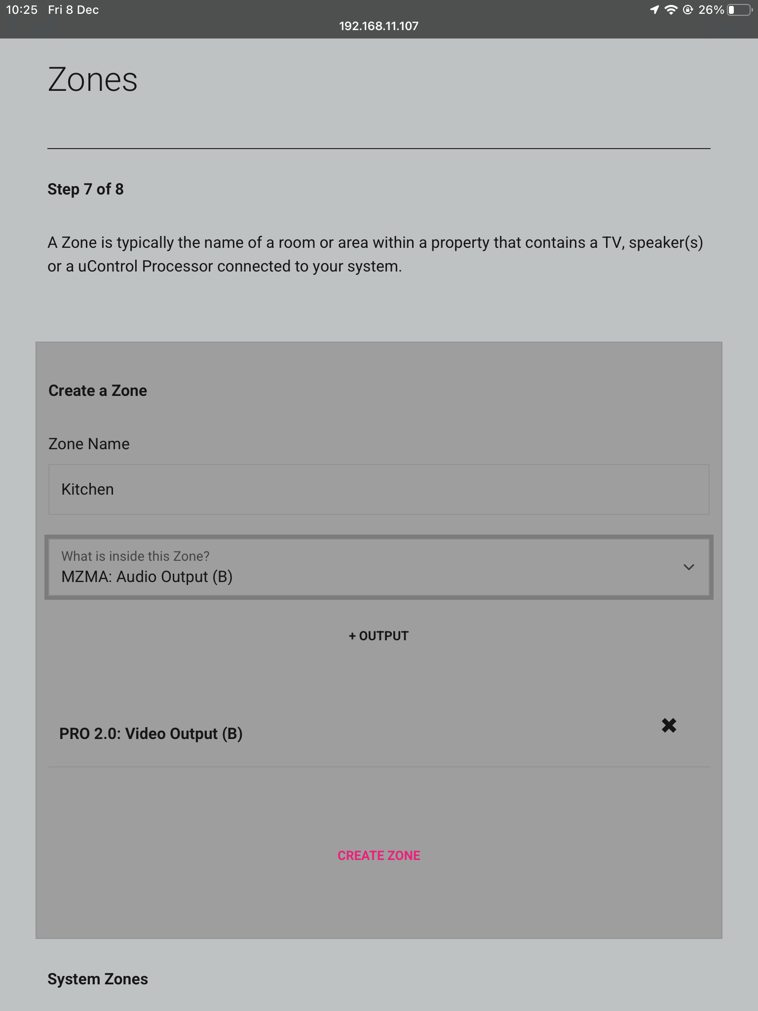
13. Zones
Name the Zones after the rooms in the property which have the device(s) plugged into the corresponding ports. For example if the kitchen has the display plugged into Video Output (B) add this to that Zone, the same goes for the audio device Audio Output (B). To add your Outputs to the Zones select them from the dropdown box and then press +OUTPUT. Repeat these steps for all Outputs and Zones.
Connect to system
Stack
Master Controller
Layers
Naming
Access uControl
Owner Account
Control Type
System Name
Connection
Manual Connections
Zones
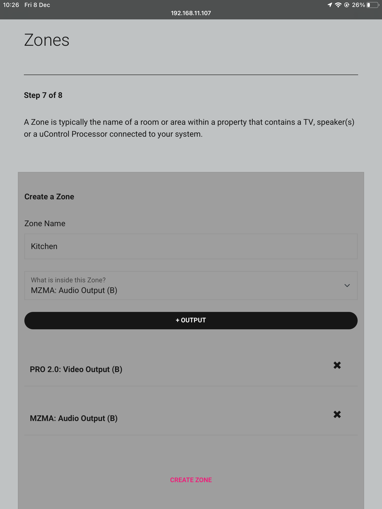
13a. Zones
Once you have added all Outputs to the zone it should look like below, press CREATE ZONE to finish.
Connect to system
Stack
Master Controller
Layers
Naming
Access uControl
Owner Account
Control Type
System Name
Connection
Manual Connections
Zones
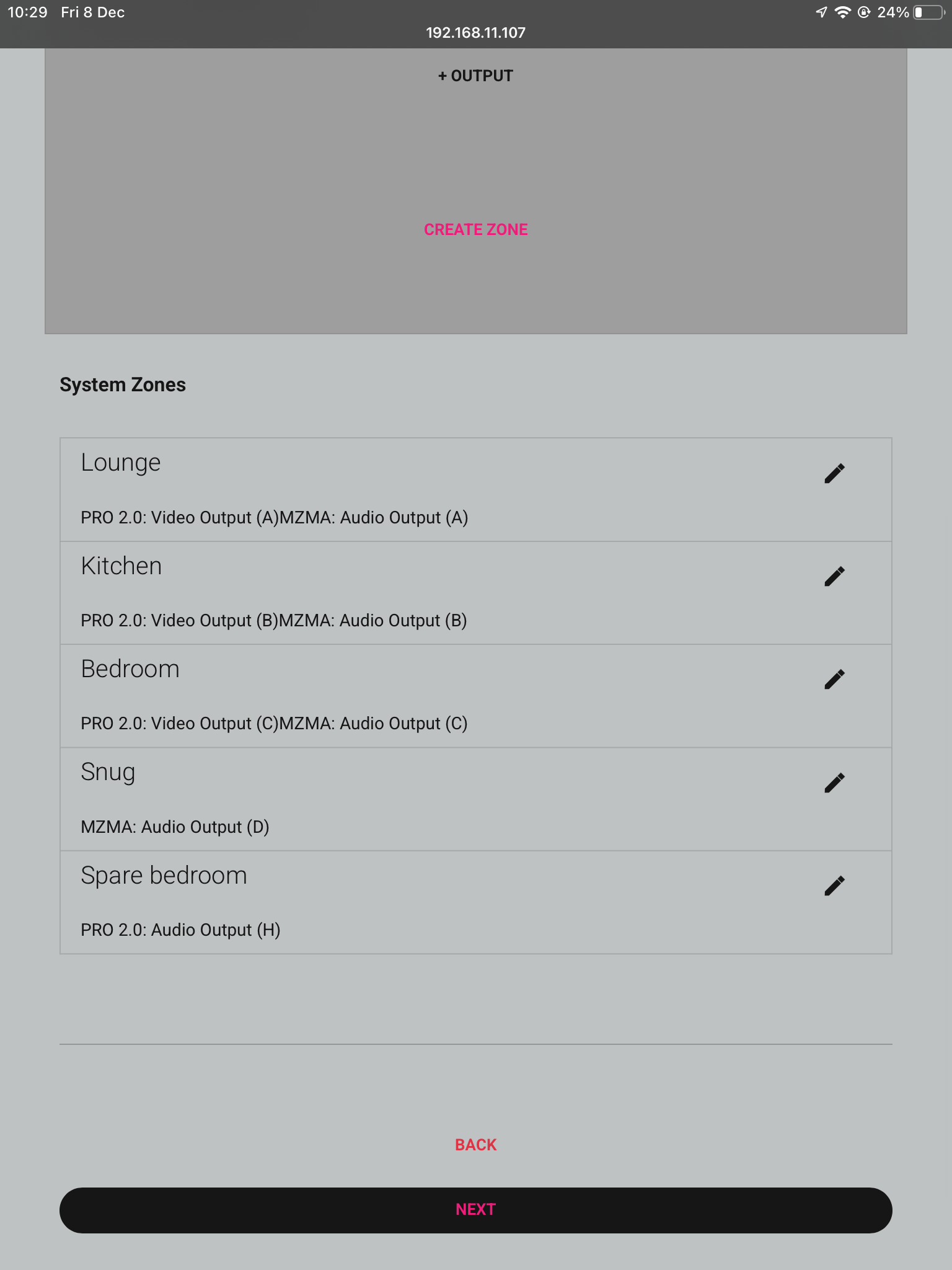
13b. Zones
Check over your zones and make sure you have assigned your devices to the correct zones.
Connect to system
Stack
Master Controller
Layers
Naming
Access uControl
Owner Account
Control Type
System Name
Connection
Manual Connections
Zones
14. Complete
Now the system has been configured press “Finish” and you will be taken out of the web interface.
Connect to system
Stack
Master Controller
Layers
Naming
Access uControl
Owner Account
Control Type
System Name
Connection
Manual Connections
Zones
Complete
15. Reboot
The last step is to remove the power cable from your Zone Processor and wait 2 minutes, then plug it back in. This is needed to apply the settings you have just changed, once the 2 minutes is up press “Continue”.
Connect to system
Stack
Master Controller
Layers
Naming
Access uControl
Owner Account
Control Type
System Name
Define Connection
Manual Connections
Zones
Complete
Reboot
After hitting continue you will be taken into the uControl interface where you can begin setting up the necessary packs and additional features like Functions and Sequences. For more guides on setting up systems after the first boot, please refer to our uOS support page.
This guide will show you how to build a stacked system using two or more MHUB S with uControl acting as the main method of control for the system.
This guide is intermediate in difficulty and assumes that you have installed MHUB before in standalone mode.
Make sure the only HDA devices on the network are the ones you want to put into the Stacked System. If you still cannot discover them in the app consider your network infrastructure, the app may struggle to find the system(s) if there are things like network switches in the residence so try simplifying it whilst going through setup.
It is strongly recommended that you read this guide carefully before commissioning your stacked system to ensure all features of the system work as expected.
the following terms are used throughout this guide.
Foundation Layer
The MHUB S system which is directly connected to a video source(s) is referred to as the Foundation Layer. Ideally, this system should be physically installed at the bottom of your MHUB S stack. Inside uOS this system is referred to as S1 (see Stack Layer below).
Connections
A Connection is used to define the cabled connections between each component in an MHUB Stack. The combination of HDA devices in your Stack will determine which ports can be paired or not.
Stack Layer
The Stack Layer is an alphanumeric identifier within uOS, starting from the Foundation Layer (Layer S1). This identifier represents the order of MHUB systems that are connected to one another by a Connection. For example, if you had four MHUB S systems stacked together, then you would start with the Foundation Layer (Layer S1), then the second MHUB S (Layer S2), followed by the third MHUB S (Layer S3) and, finally, the fourth MHUB S (Layer S4).
IR Cascade
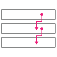
MHUB S supports infrared (IR) passback from any display receiver connected to any MHUB system to another MHUB, through a process called IR Cascading. IR Cascading works from the top of your Stack, down the MHUB Stack Layers, until it reaches the Foundation Layer Source IR outputs or is instructed to stop elsewhere by uOS.
Master / Controller
An HDA device (like a Zone Processor) designed to control MHUB and/or MZMA systems operating in Stack mode. Any Stack that needs to be controlled by uControl must have a Master / Controller present in your setup. This is identified as M1 in uOS.
uControl
uControl is our control system for configuration and control of stacked systems. When we refer to “uControl” in this article we are referring to our app specifically.
Wiring
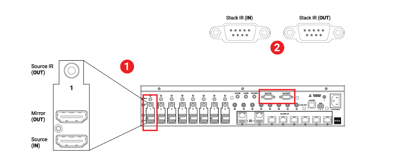
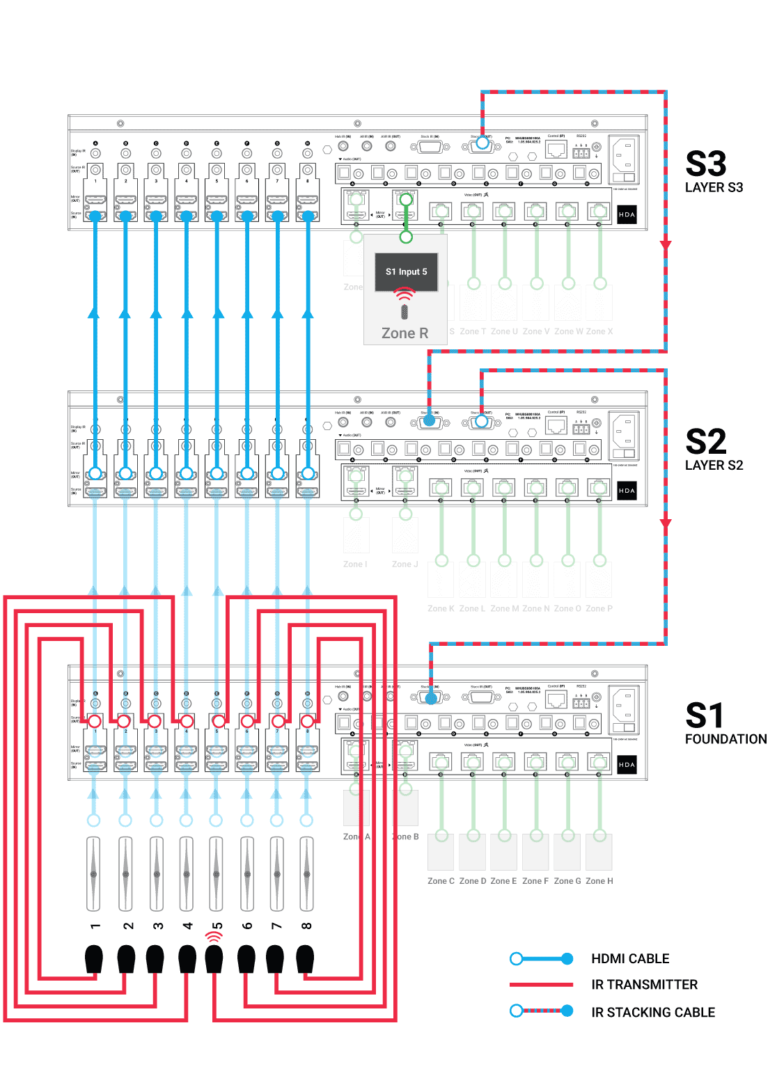
Stacking video and cascading IR is made possible by two ports on the rear of each MHUB S.
“Mirror (OUT)” port
Connect the mirror out HDMI port to each Source Input at the Foundation Layer MHUB to the corresponding Source In HDMI port of the next MHUB in the stack.
“Stack IR (IN)” & “Stack IR (OUT)” ports
(Only needed if you are using IR Passback in your stack)
Used for MHUB S’ IR Cascading function and can be connected using the Source IR Stacking Cable included with MHUB S. Stack IR only works with a maximum of 4 MHUB S systems.
Figure 1: Ports used for stacking video and transporting IR commands (cascade). You will need to identify these ports to stack into other MHUB systems
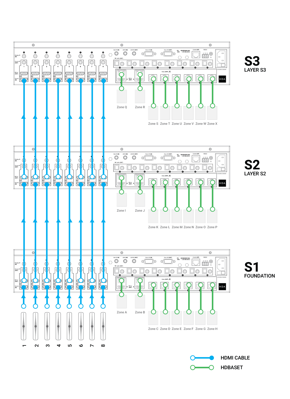
Using HDMI cables, connect your video input/source to the lowest MHUB in your stack (Foundation Layer) first. Connect them to the “Source (IN)” port.
Repeat step 1 for every video/input source.
From the Foundation Layer locate the “Mirror (OUT)” port and connect a short HDMI cable to it. Complete this connection by connecting the HDMI cable to the “Source (IN)” port on the MHUB S in the layer above.
Repeat step 3 for every MHUB S in your stack.
Figure 2: (8×24) system wiring example: Connect from the Foundation Layer UP the MHUB S stack as many times as neeeded.
Watch video: How to wire MHUB S to create a stack
This video describes how to wire MHUB S systems together to create a stack.
Watch video: IR Cascading
If you plan to control your video input/sources using the original source remote control from displays served by stacked MHUB S then you will need to cascade IR down your stack.
There are some general rules to follow when doing this:
Cascading IR applies to source control only. You cannot Cascade IR to displays.
Cascading IR goes down the Stacking Layers only, from last to first.
Similar to Connections, IR Cascading can only be defined between incremental Stacking Layers: S3 to S2 and finally S1. It is not possible to jump between devices, for example, S3 to S1.
The Source IR Stacking Cable is 50cm/1.64ft so bear this in mind when rack mounting MHUB S, you must use the one supplied with the full kit.
All “Source IR (OUT)” ports have two modes: Local and Passthrough. If the port is set to Local, then any IR received from a stacked MHUB will be transmitted on the receiving MHUB. If the port mode is Passthrough then the IR signal will be transported off that MHUB down the Stack Layer until it reaches an instruction to execute the IR command Locally.
IMPORTANT: Local and Passthrough modes can be set from uOS on the Zone Processor.
Any input served from a “Mirror (Out)” port must match the “Source (IN)” port identifier. You can not switch port IDs (eg. Mirror 1 to Input 4)
Figure 3: In this 8×24 system a native video source remote control (in Zone R) is being used to send IR commands through the MHUB S stack from S3 back to S1 Foundation Layer and correctly sent to the source being watched in Zone R.
How to wire MHUB S for IR cascading
This video describes how to send IR from a stacked MHUB S to the Foundation Layer.
Initialising your Stacked System using uControl
Ensure that your MHUB S systems are correctly wired for stacking covered in the part above and that the following is completed:
All MHUB S systems in your stack are powered ON.
Your Master / Controller device (Zone Processor or uControl Connect) is powered ON.
All MHUB S systems and the Master Controller are all connected to the LAN and reachable by their IP address.
IMPORTANT: All hardware has been individually updated to the latest software version.
Configuring MHUB to operate in stacked mode can not be undone without resetting the system and starting again. Ensure that you have your wiring information handy and that you know exactly how the system is connected together before initialising your stack.
1. Connect to system
To get started press connect to system on the uControl Homepage.
Connect to system
2. Stack
If the HDA devices are on the network you will be presented with the option to create a stack, video standalone or audio standalone, as this contains two MHUB S’ it is a Stack.
Connect to system
Stack
3. Master Controller
The Zone Processor acts as the bridge between 2 or more HDA devices and all data goes through this device, acting as a brain. It needs to be selected as the Master Controller.
Connect to system
Stack
Master Controller
4. Setting Stack Layers
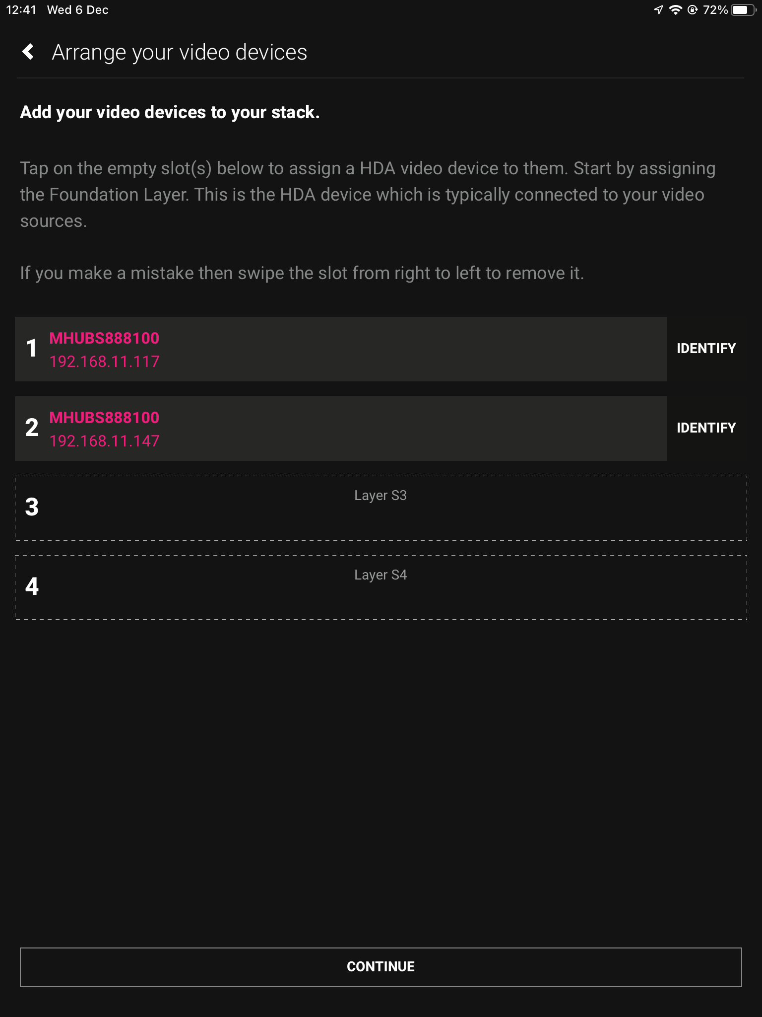
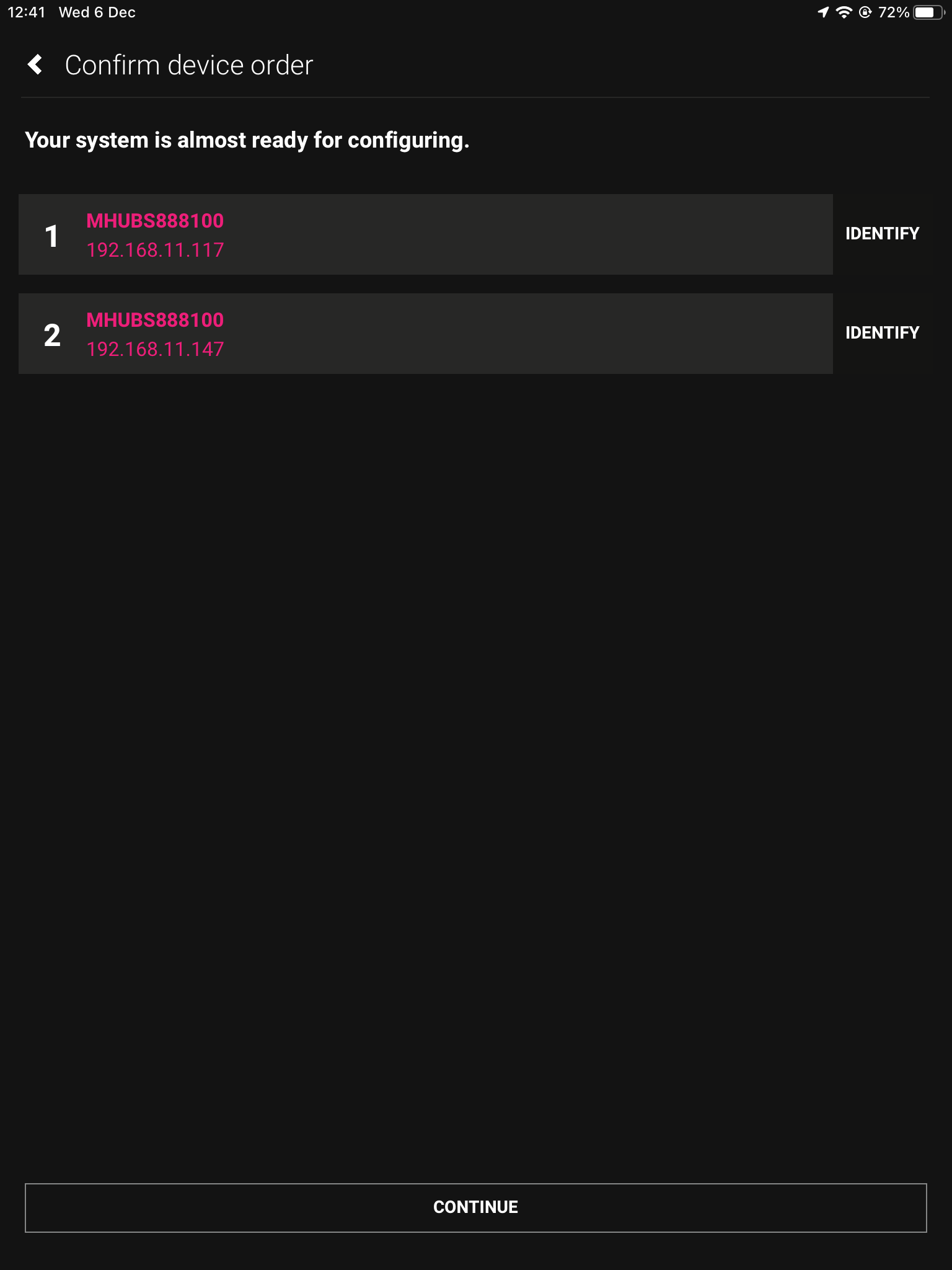
Next we need to choose our layers, starting with the Foundation Layer. Press identify to the right of the HDA device to make the power LED blink, when you know which is which select your primary MHUB for 1 and the other HDA device for 2, then hit continue.
Connect to system
Stack
Master Controller
Layers
4b. Order of layers
The order of your physical stack may be different to the order in uControl, as the MHUB with the IP address 192.168.11.147 could be the Foundation layer. It is important to mirror the order of the MHUB’s.
Connect to system
Stack
Master Controller
Layers
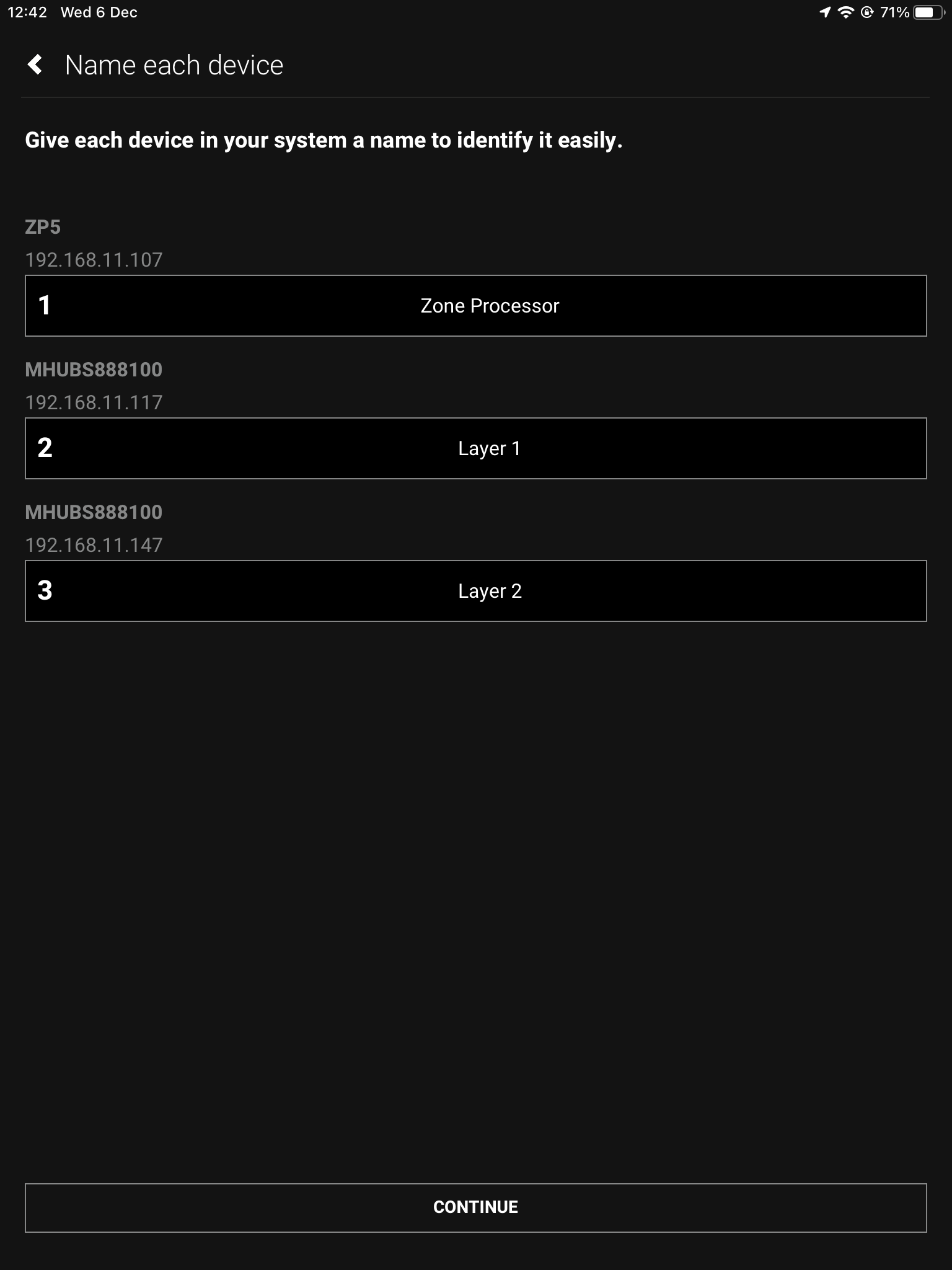
5. Naming devices
Name the devices so that they’re easily identifiable.
Connect to system
Stack
Master Controller
Layers
Naming
6. Access uControl
Your MHUB’s are now in Stack mode and are ready for configuration. You can now proceed to perform First Boot of your Stack with the Master Controller (M1)
Connect to system
Stack
Master Controller
Layers
Naming
Access uControl
7. Owner Account
Owner Accounts allow installers to add their HDA PRO account to their system for additional features, and to increase the warranty period. We recommend you do not skip this step.
Connect to system
Stack
Master Controller
Layers
Naming
Access uControl
Owner Account
8. Control Type
Choose uControl as the Control Type.
Connect to system
Stack
Master Controller
Layers
Naming
Access uControl
Owner Account
Control Type
9. System Name
Confirm the names of your devices.
Connect to system
Stack
Master Controller
Layers
Naming
Access uControl
Owner Account
Control Type
System Name
10. Setup Connections
This next step will allow us to make the manual connections between the multiple devices.
Connect to system
Stack
Master Controller
Layers
Naming
Access uControl
Owner Account
Control Type
System Name
Connections
11. Manual Connections
This is where you tell the system how it is all linked. In this example source device 1 will be connected to Source (In)1 of the first layer (S1) in the stack and then mirrored with a shorter HDMI cable going into Source (In)1 of the second layer (S2), meaning the source will be available on both MHUB’s and therefore more zones. The same goes for Input 2 being paired with Source 2 on the second layer. Make sure to repeat how ever many times needed for your amount of source devices.
Connect to system
Stack
Master Controller
Layers
Naming
Access uControl
Owner Account
Control Type
System Name
Connection
Manual Connections
12. Zones
A zone is where a display is located, so name the zones after the room those displays are in. To add an output to a zone, choose which output from the list and then press “+OUTPUT”, check that the output has been added below in bold and then press “Create Zone”. Repeat process for all zones.
Connect to system
Stack
Master Controller
Layers
Naming
Access uControl
Owner Account
Control Type
System Name
Connection
Manual Connections
Zones
13. Complete
Now the system has been configured press “Finish” and you will be taken out of the web interface.
Connect to system
Stack
Master Controller
Layers
Naming
Access uControl
Owner Account
Control Type
System Name
Connection
Manual Connections
Zones
Complete
14. Reboot
The last step is to remove the power cable from your Zone Processor and wait 2 minutes, then plug it back in. This is needed to apply the settings you have just changed, once the 2 minutes is up press “Continue”.
Connect to system
Stack
Master Controller
Layers
Naming
Access uControl
Owner Account
Control Type
System Name
Define Connection
Manual Connections
Zones
Complete
Reboot
After hitting continue you will be taken into the uControl interface where you can begin setting up the necessary packs and additional features like Functions and Sequences. For more guides on setting up systems after the first boot, please refer to our uOS support page.
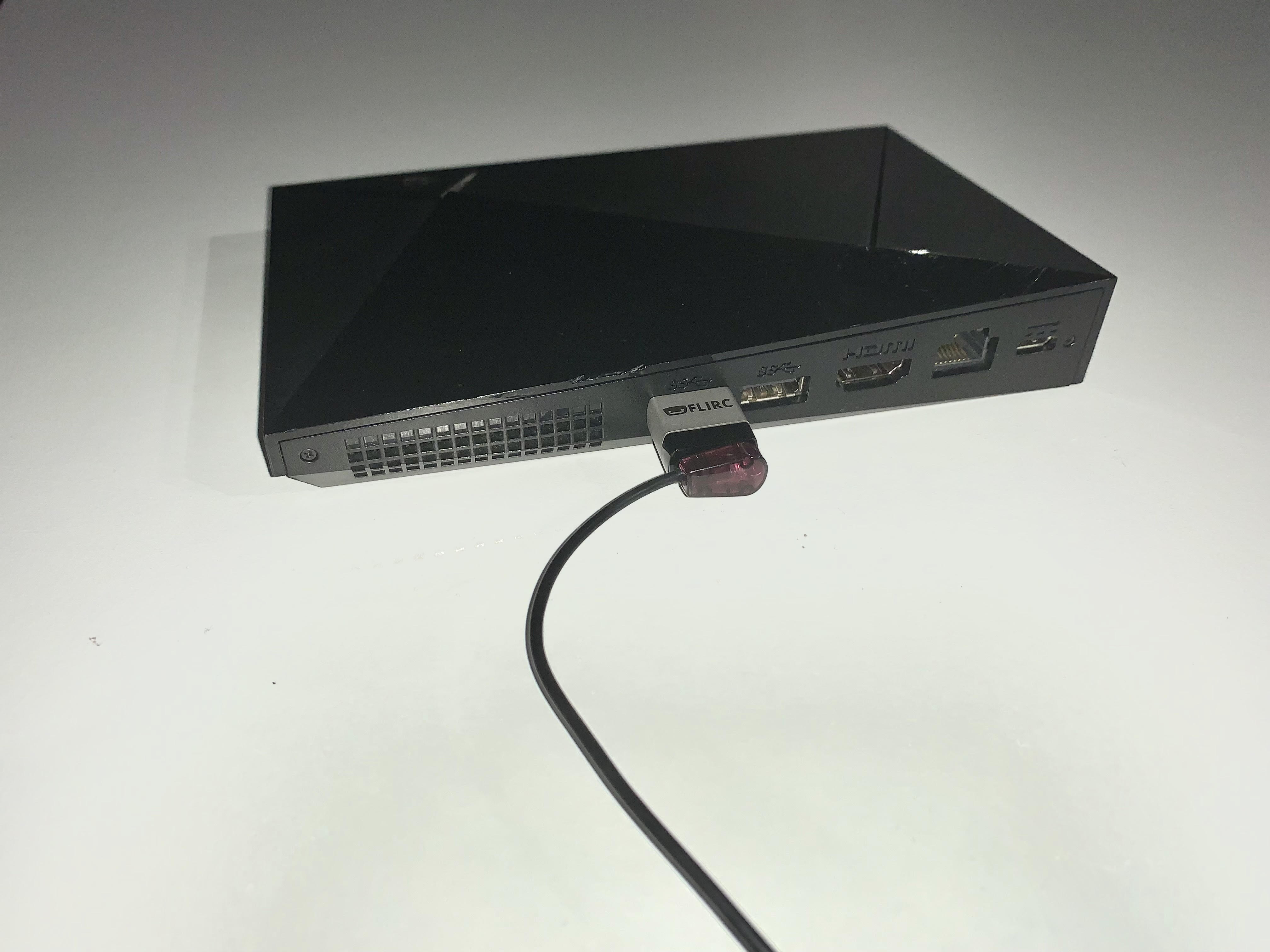
Some devices no longer have built in IR receivers. To enable them to be used with the uControl app you can add a third party device called FLIRC. This connects to a source device via USB and turns IR codes into control commands the source device recognises.
Load up the Flirc software and in the top left click File, and then Load Configuration and choose the NVIDIA Shield profile you have just downloaded
Remove your Flirc from the laptop/PC and connect it to the female USB port on the back of your NVIDIA Shield. Next place the IR transmitter from you HDANYWHERE device on or near to the Flirc.
Once this is done you can install the NVIDIA Shield IR pack and control your NVIDIA device with uControl.
If your HDA device has uControl, you can download IR or IP packs to control thousands of third party devices from the interface of the uControl mobile app. In this guide you will see how to browse our extensive library to download and control the packs for your devices.
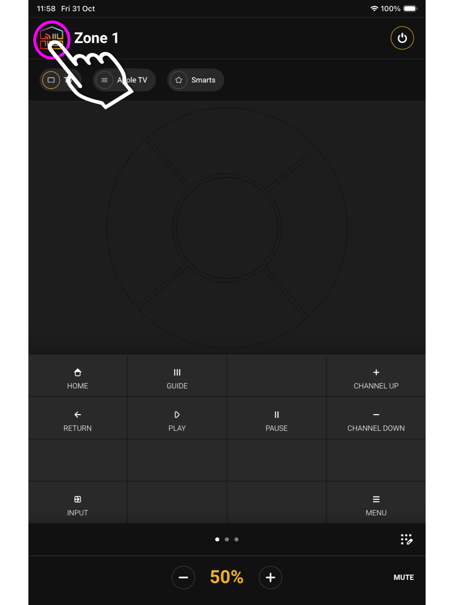
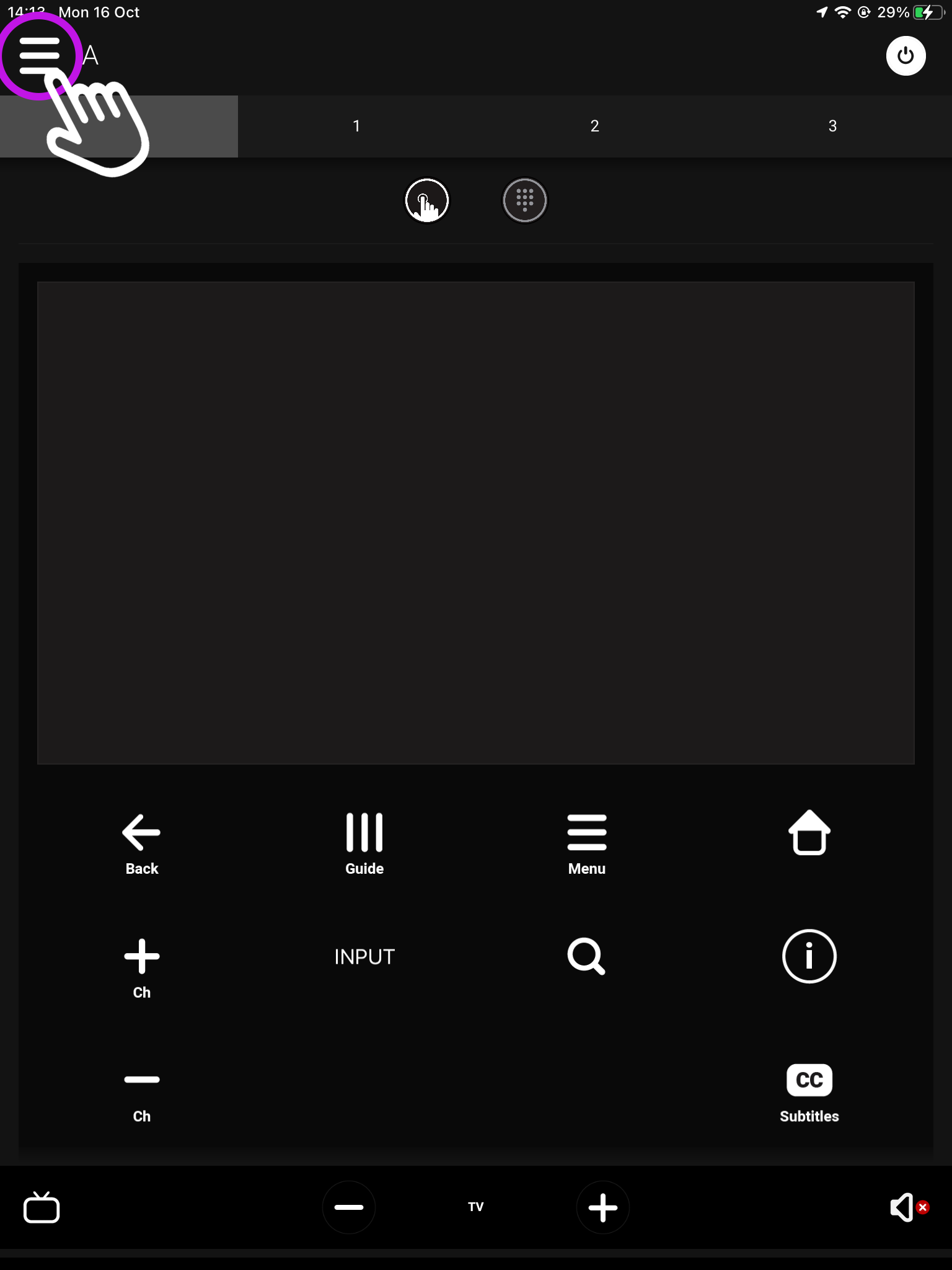
From the main screen navigate to the menu in the top left.
Open uControl
What you see on the main screen may differ, however, the house icon will still be there.
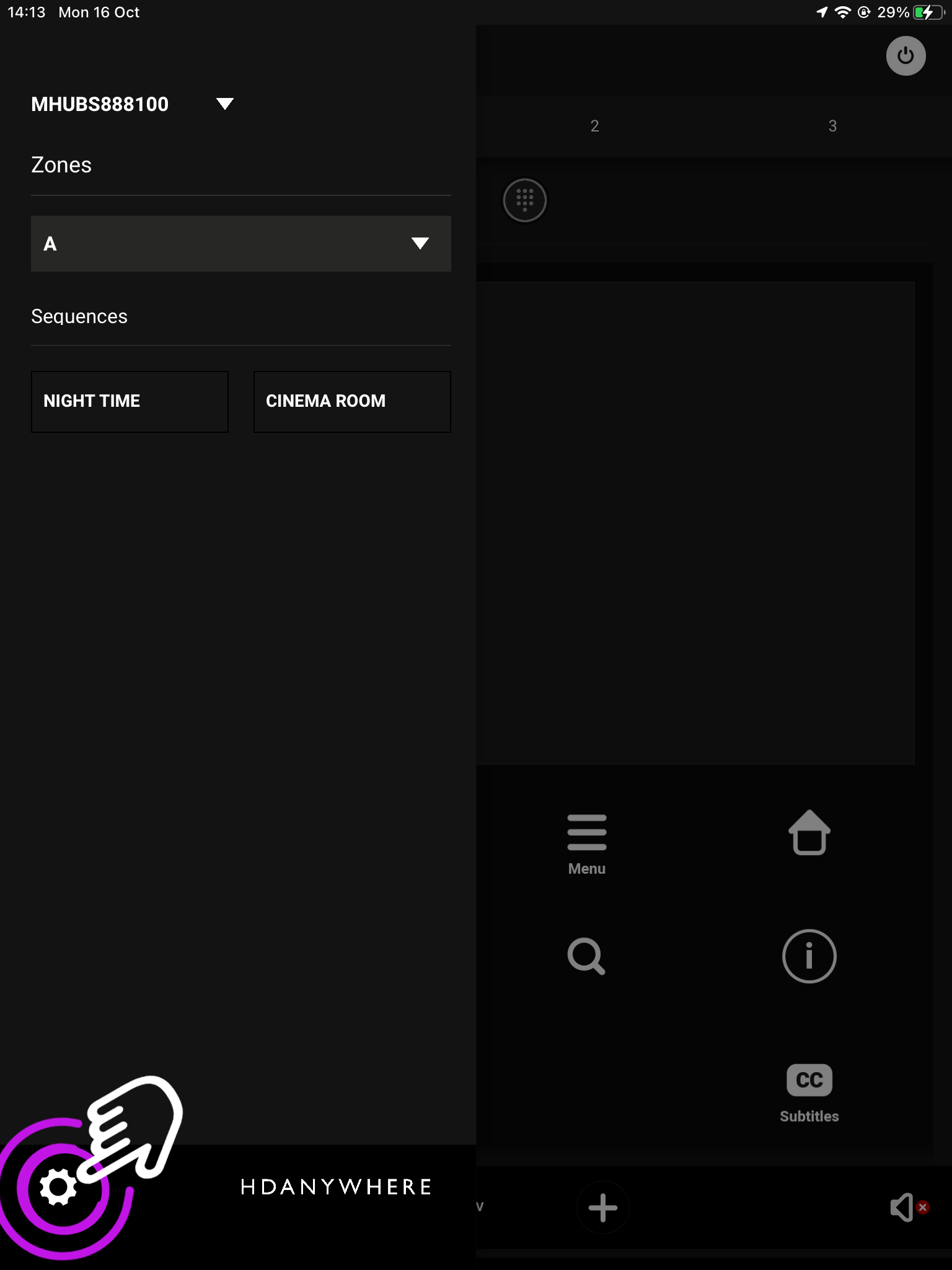
2. Navigate to your settings
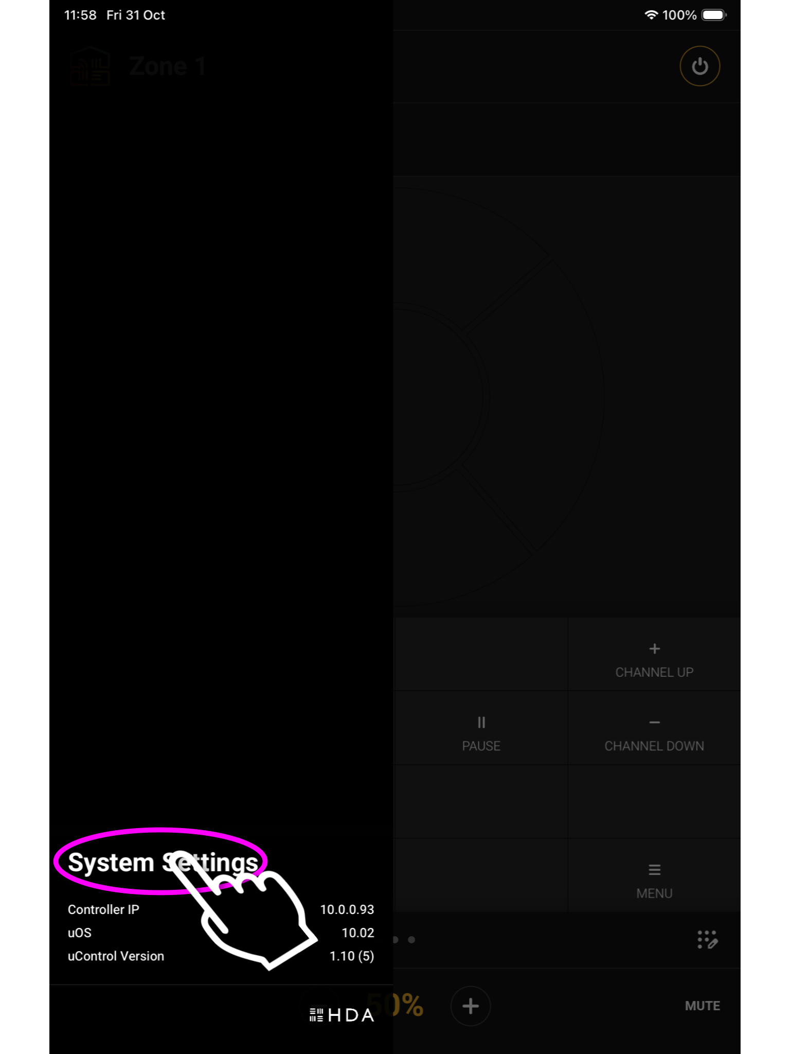
Look for ‘System Settings’ located in the bottom left corner.
Open uControl
Settings
It will be in the bottom left corner.
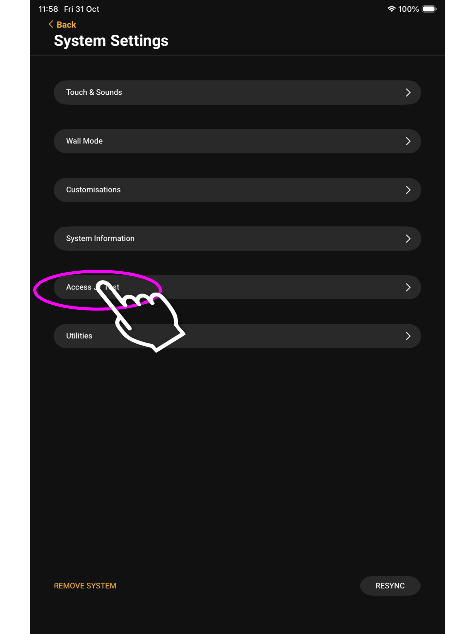
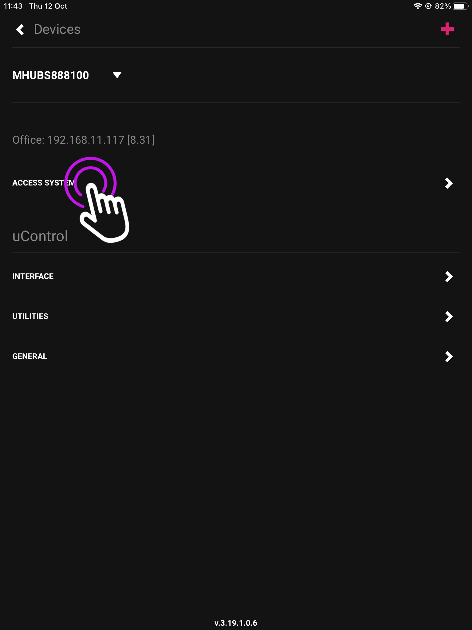
3. Access System
From here press Access System.
Open uControl
Settings
Access System
Click Access [system name], the name you configured in uOS will be shown here
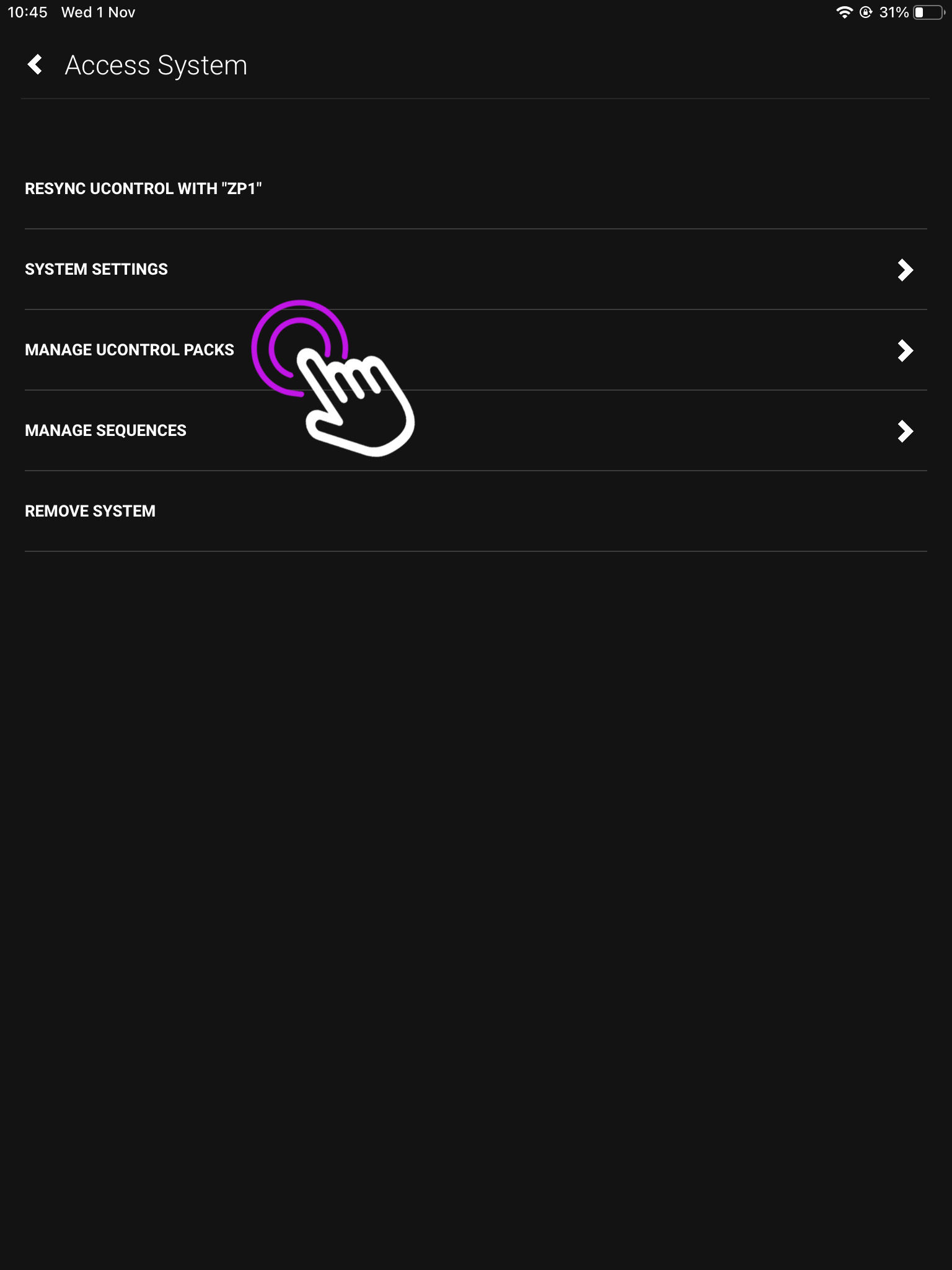
4. uControl Packs
In this menu press “Manage uControl Packs”.
Open uControl
Settings
Access System
uControl Packs
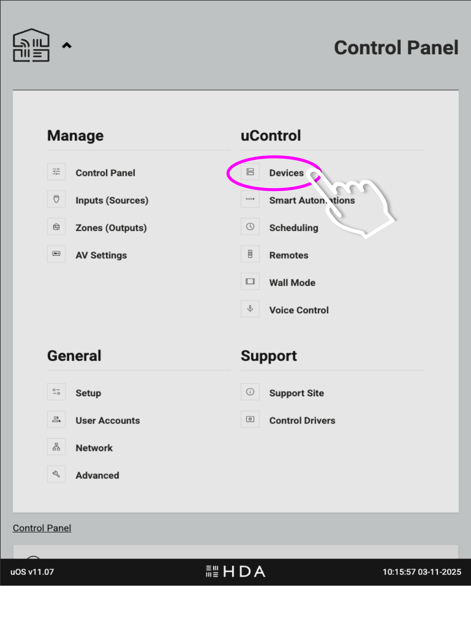
Open the menu and select ‘Devices’. This will take you to the page where you can download IR and IP packs, and also create IP connections for integrating 3rd party controllers.
5. Add New
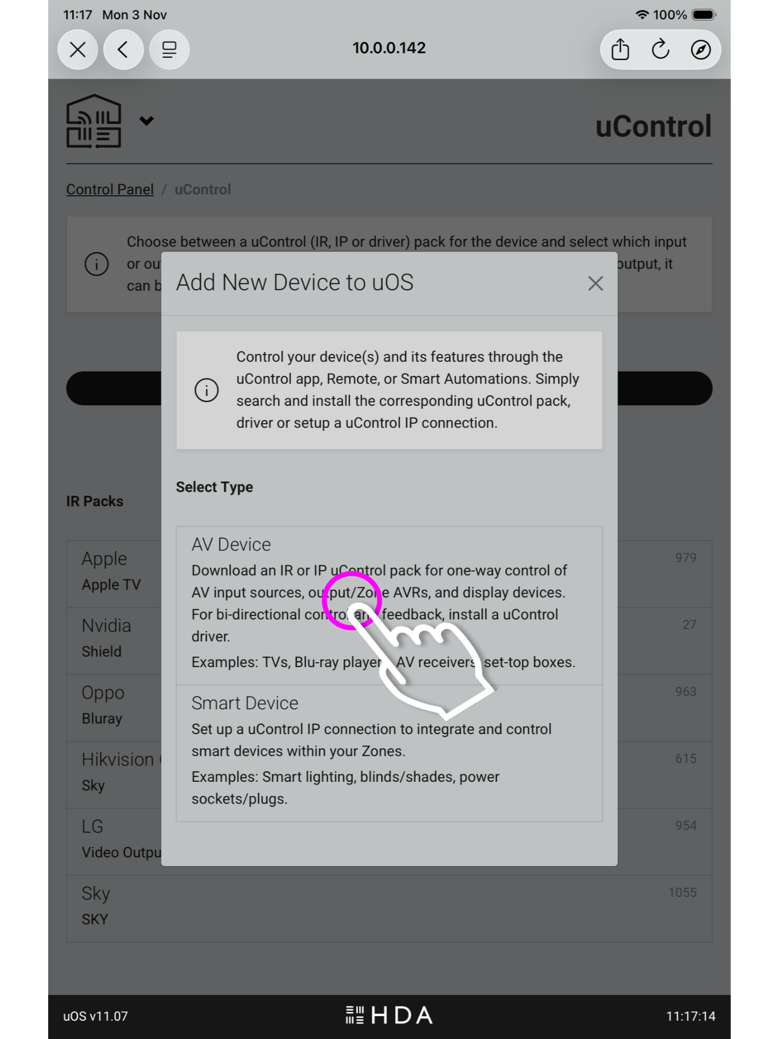
Now we are in uOS press Add New and a pop up window will appear, press AV Device.
Open uControl
Settings
Access System
uControl Packs
Add New
The below option (Smart Device), is for integrating third party controllers to be controlled by uOS.
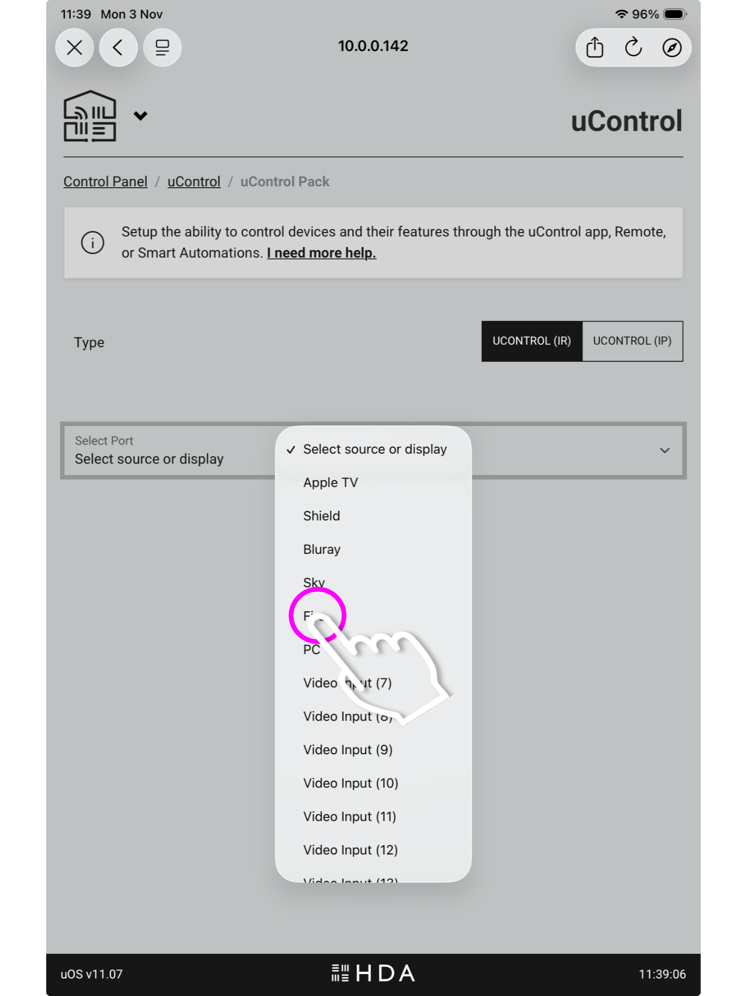
6. Port Select
You must now select if you’re installing a pack for a source device,a display/output or assigning it to a zone.
Open uControl
Settings
Access System
uControl Packs
Add New
Ports
You may have labelled your ports after the sources plugged into the HDA device in the setup like above, or they may remain named numerically.
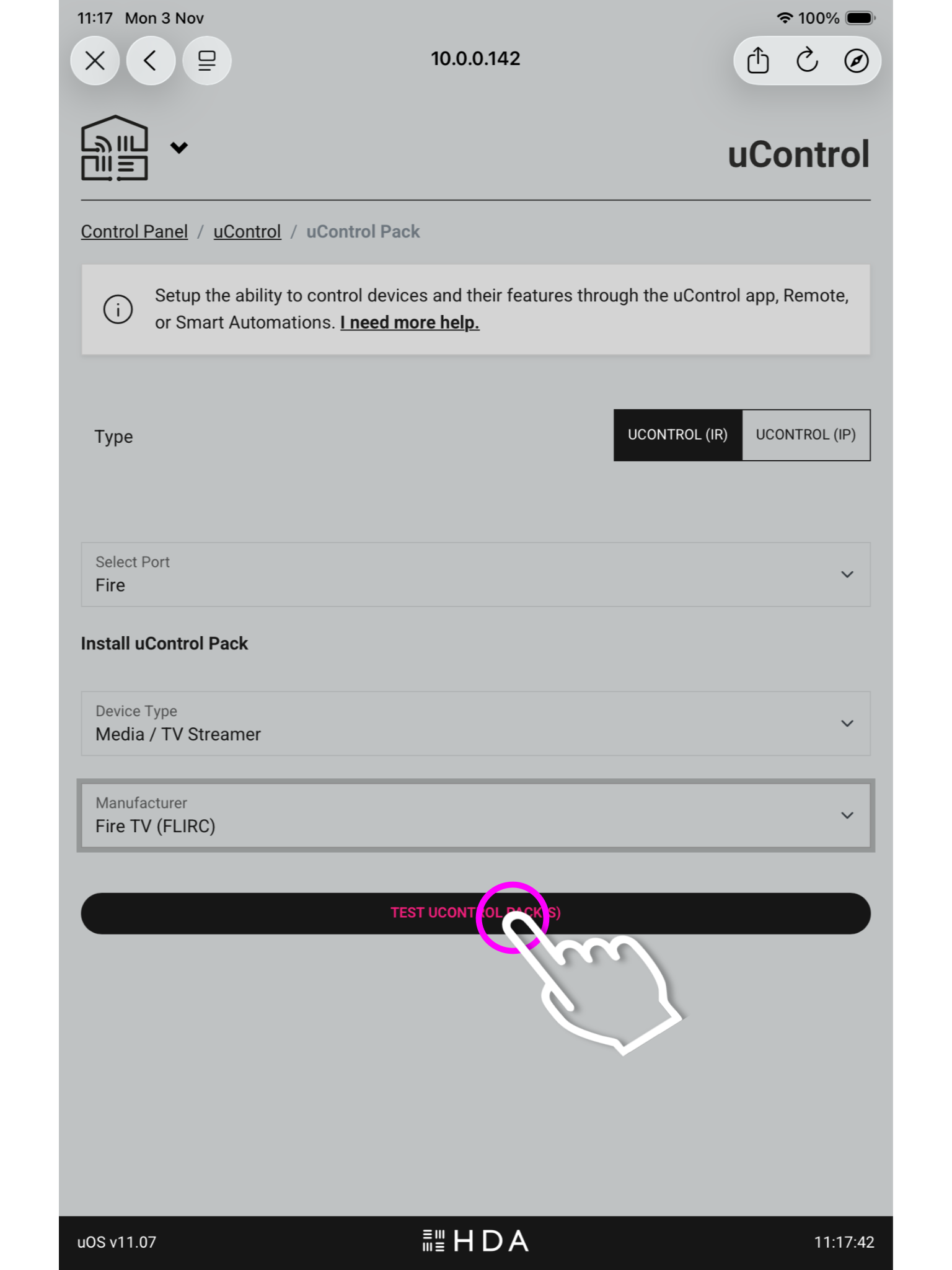
7. Pack Information
Once you have chosen the port you need to select the device type and its manufacturer then press install.
Open uControl
Settings
Access System
uControl Packs
Add New
Ports
Pack Info
In the top right you will see the option to switch between IR and IP packs.
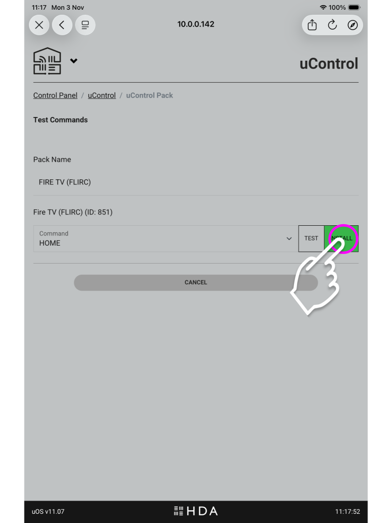
8. Testing the pack
The last step is to test the commands to make sure you have the correct pack installed, if you get a response press install.
Open uControl
Settings
Access System
uControl Packs
Add New
Ports
Pack Info
Test
If you do not see a response, ensure you have the IR trasnmitter plugged into the correct “Source IR Out” port and have the bud itself covering the IR window of the source device.
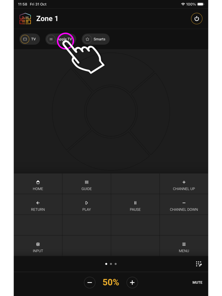
9. Using the pack in uControl Homepage
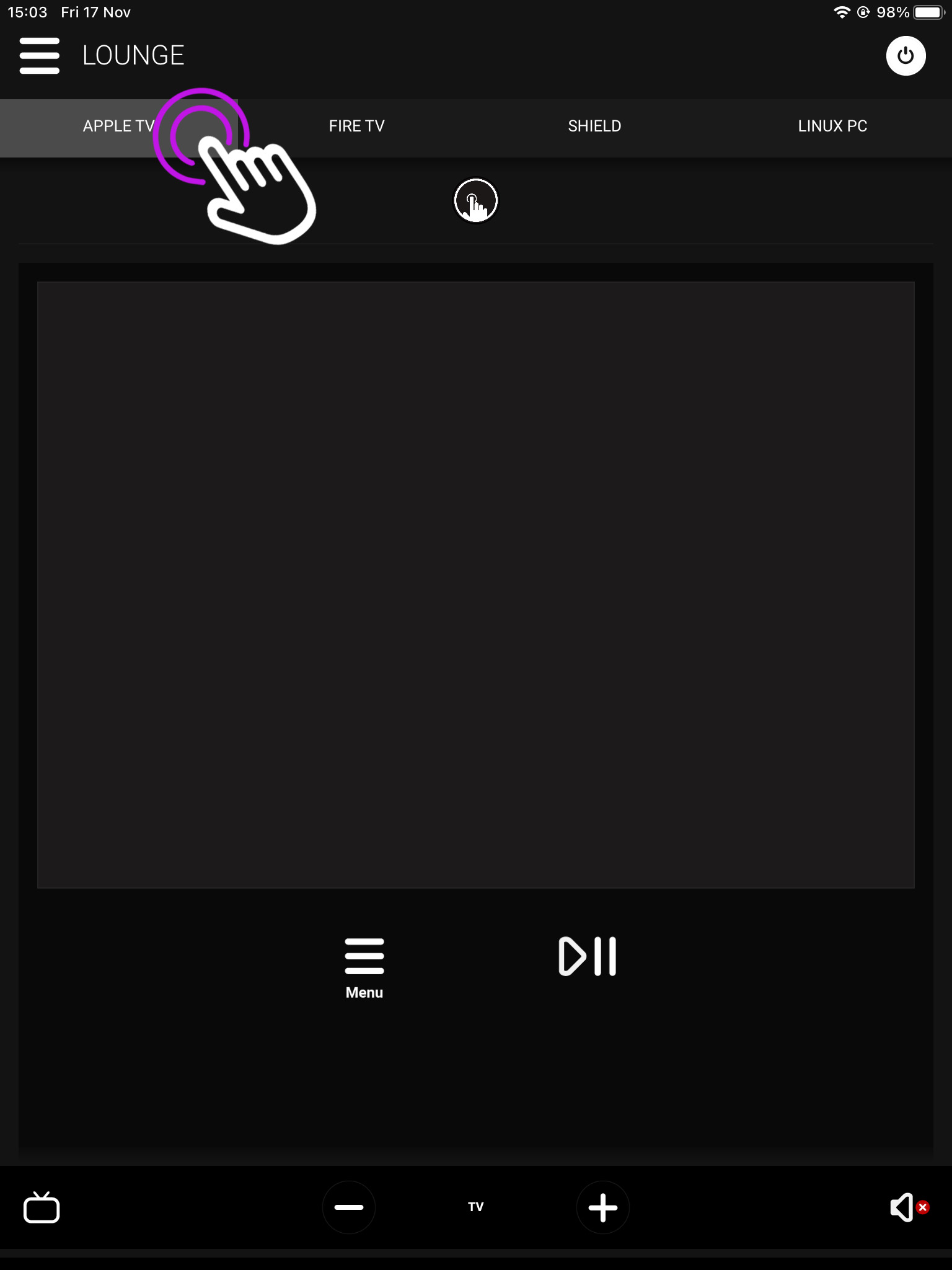
You will see your available sources at the top of the uControl Homepage, and you can use these icons to switch between inputs.
Open uControl
Settings
Access System
uControl Packs
Add New
Ports
Pack Info
Test
uControl Homepage
The pack UI will have the buttons which would appear on the remote, along with a gesture box for navigation and volume controls located at the bottom.
Installing uControl Packs from uControl
1. Open uControl
From the main screen navigate to the menu in the top left.
Open uControl
What you see on the main screen may differ, however, the three lined menu bar will still be there.
2. Navigate to your settings
Look for the settings icon located in the bottom left corner.
Open uControl
Settings
The icon may vary depending on your mobile devices size, although it will still be in the bottom left corner.
3. Access System
From here press Access System.
Open uControl
Settings
Access System
This is your device page which displays your units model and IP address.
4. uControl Packs
In this menu press “Manage uControl Packs”.
Open uControl
Settings
Access System
uControl Packs
This will take you to the page where you can download IR and IP packs, and also create IP connections for integrating 3rd party controllers.
5. Add New
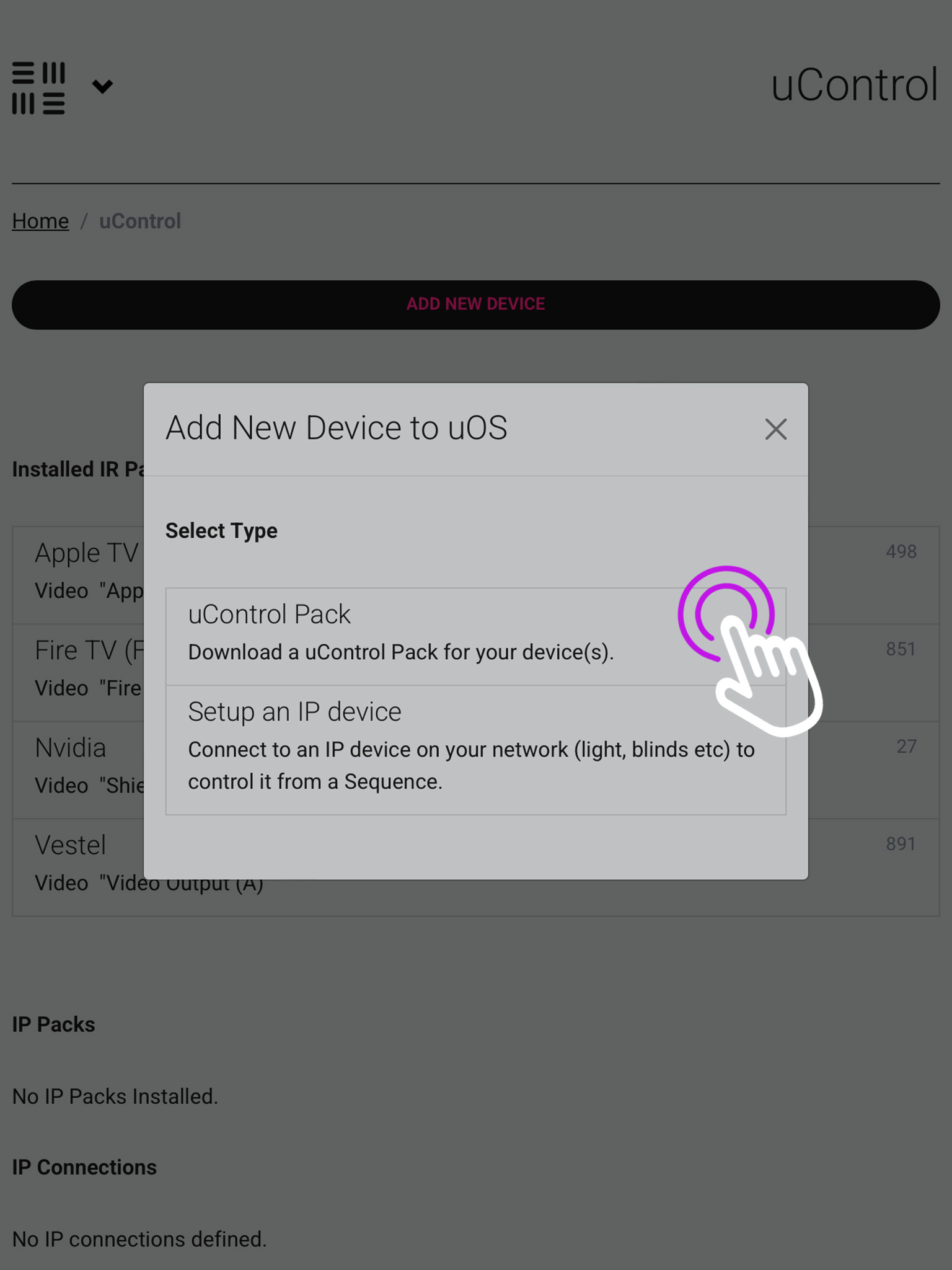
Now we are in uOS press Add New and a pop up window will appear, press uControl Pack.
Open uControl
Settings
Access System
uControl Packs
Add New
The below option (Setup an IP device), is for integrating third party controllers to be controlled by uOS.
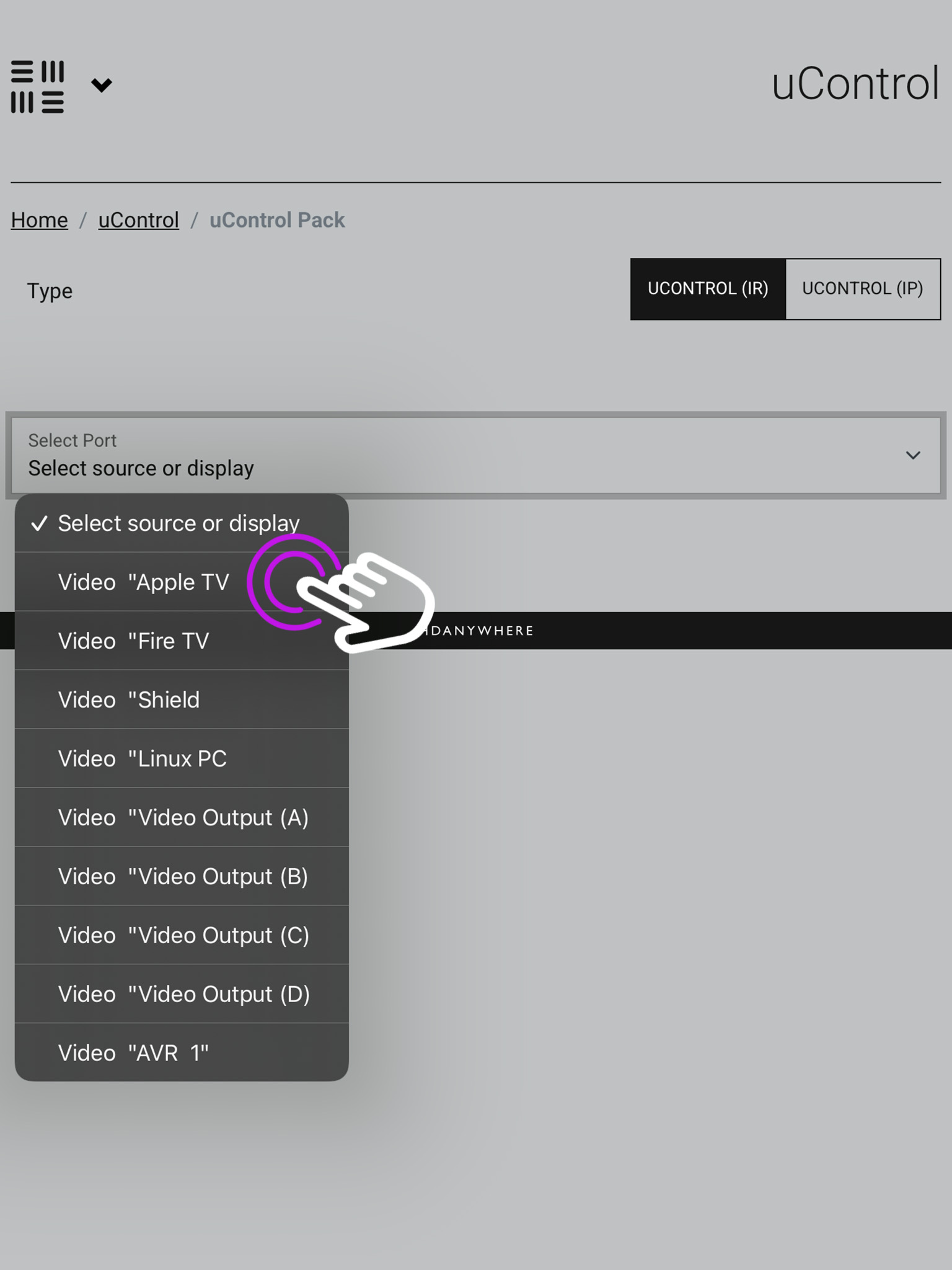
6. Port Select
You must now select if you’re installing a pack for a source device or a display/output.
Open uControl
Settings
Access System
uControl Packs
Add New
Ports
You may have labelled your ports after the sources plugged into the HDA device in the setup like above, or they may remain named numerically.
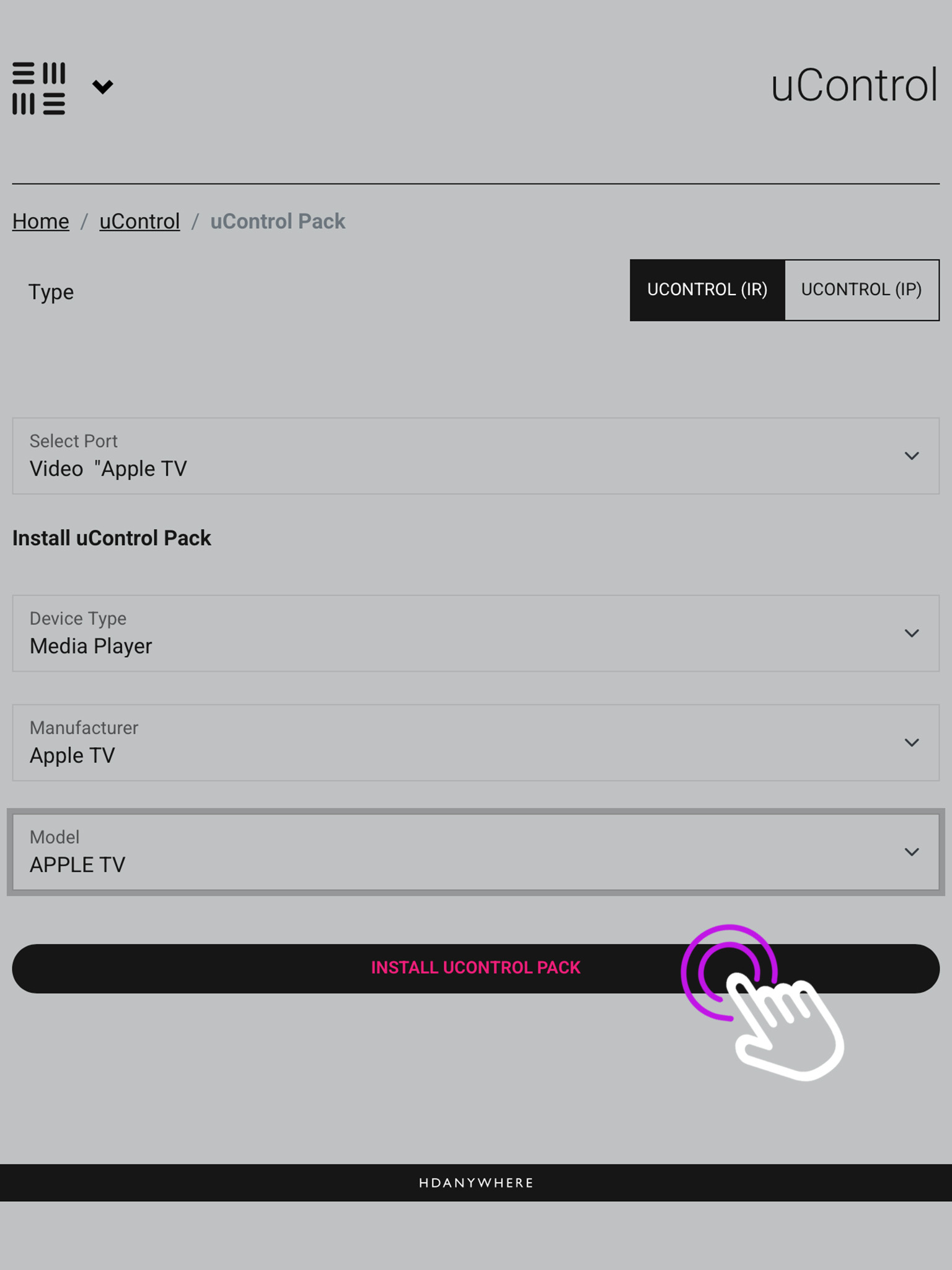
7. Pack Information
Once you have chosen the port you need to select the device type, its manufacturer and model then press install.
Open uControl
Settings
Access System
uControl Packs
Add New
Ports
Pack Info
In the top right you will see the option to switch between IR and IP packs.
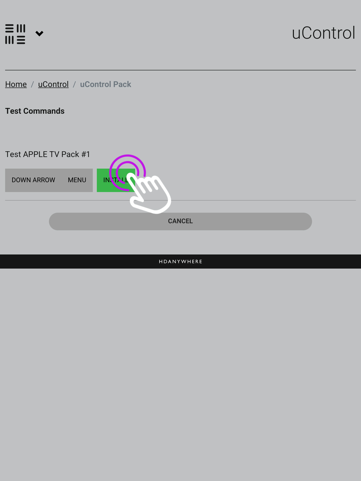
8. Testing the pack
The last step is to test the commands to make sure you have the correct pack installed, if you get a response press install.
Open uControl
Settings
Access System
uControl Packs
Add New
Ports
Pack Info
Test
If you do not see a response, ensure you have the IR trasnmitter plugged into the correct “Source IR Out” port and have the bud itself covering the IR window of the source device.
9. Using the pack in uControl Homepage
You will see your available sources at the top of the uControl Homepage, and you can use these icons to switch between inputs.
Open uControl
Settings
Access System
uControl Packs
Add New
Ports
Pack Info
Test
uControl Homepage
The pack UI will have the buttons which would appear on the remote, along with a gesture box for navigation and volume controls located at the bottom.
If your HDA device has uControl, you are able to use Functions which allow you to manage the on/off, up/down, mute/unmute and open/close state of your devices and include them into your sequences.
From the main screen navigate to the menu in the top left.
Open uControl
What you see on the main screen may differ, however, the three lined menu bar will still be there.
2. Navigate to your settings
Look for the settings icon located in the bottom left corner.
Open uControl
Settings
The icon may vary depending on your mobile devices size, although it will still be in the bottom left corner.
3. Access system
From here press “Access System”.
Open uControl
Settings
Access system
This is your device page which displays your units model and IP address.
4. Sequences
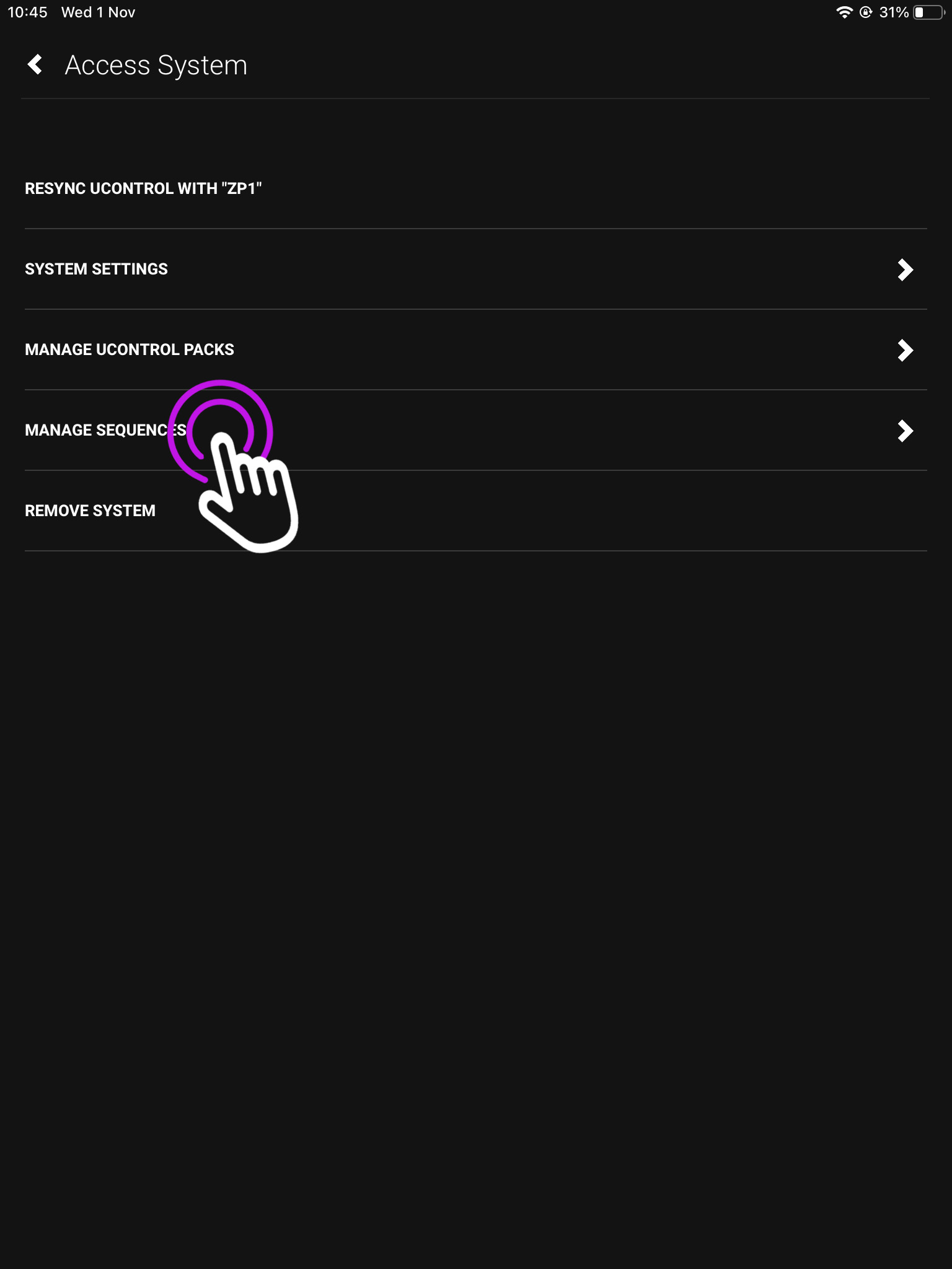
In this menu press “Manage Sequences”.
Open uControl
Settings
Access system
Sequences
This will take you to the page where you manage both Sequences and Functions.
5. webUI
The webUI can also be easily accessed by typing you devices IP address into a website URL.
Open uControl
Settings
Access system
Sequences
webUI
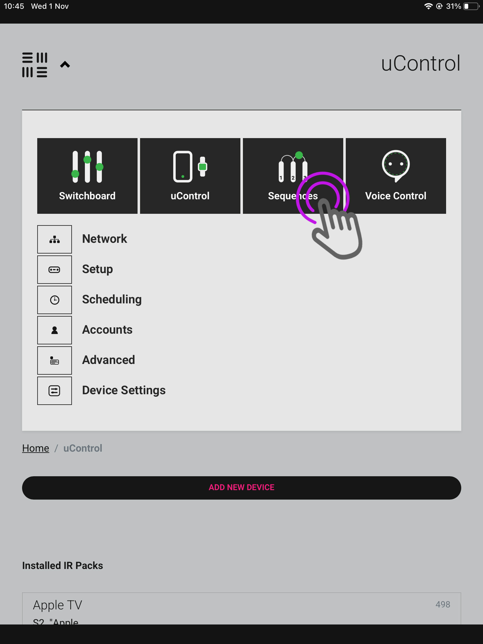
You will be taken to the uOS home page, open the menu in the top left and select “Sequences”.
6. Add new
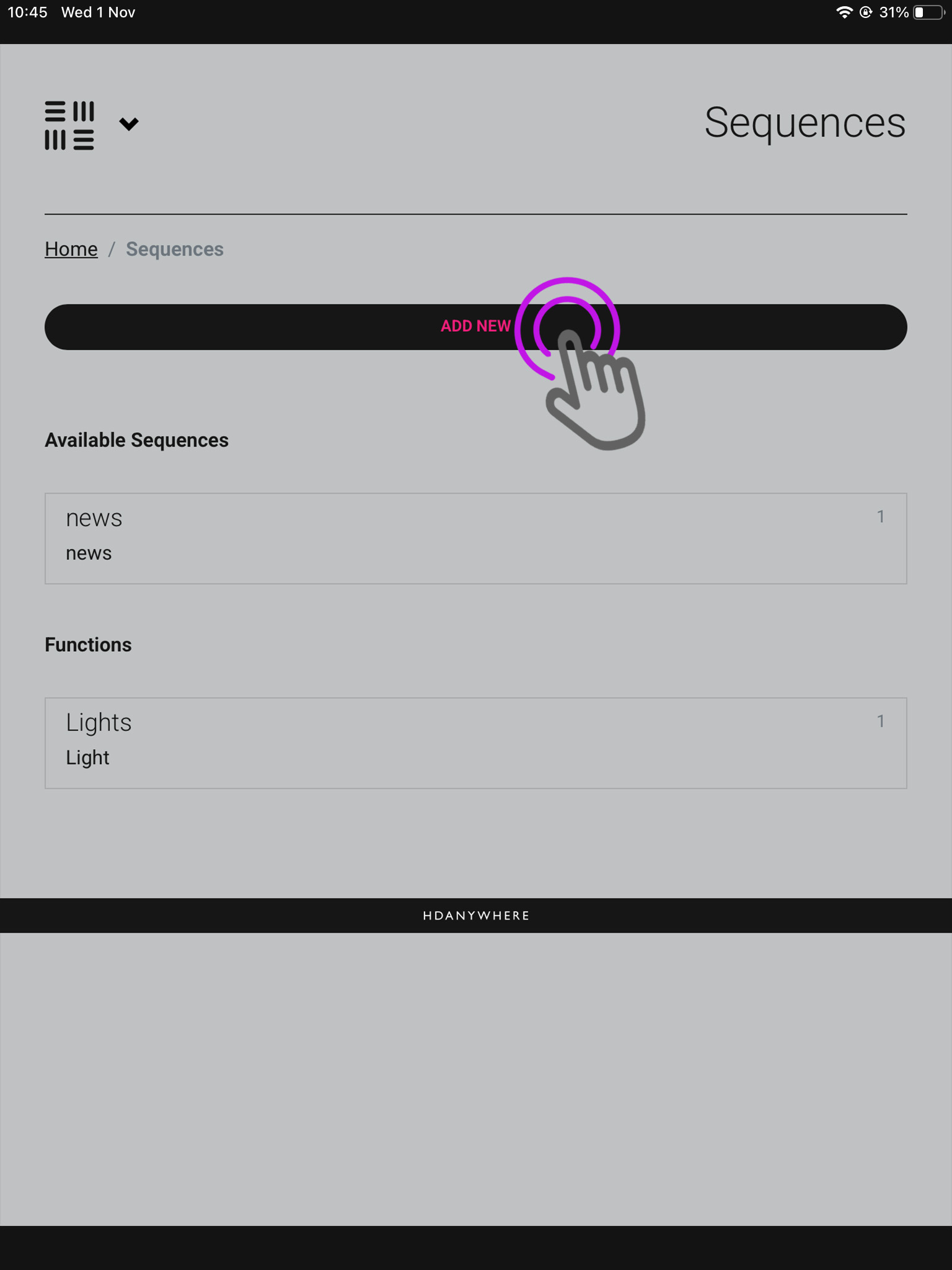
We are now in the sequences page where you can see your available sequences, and current functions. Press “Add New”.
Open uControl
Settings
Access system
Sequences
webUI
Add new
A pop-up will appear asking if you’re creating a Function or Sequence, choose Function.
7. Functions
Now we need to create your Function.
Open uControl
Settings
Access system
Sequences
webUI
Add new
Functions
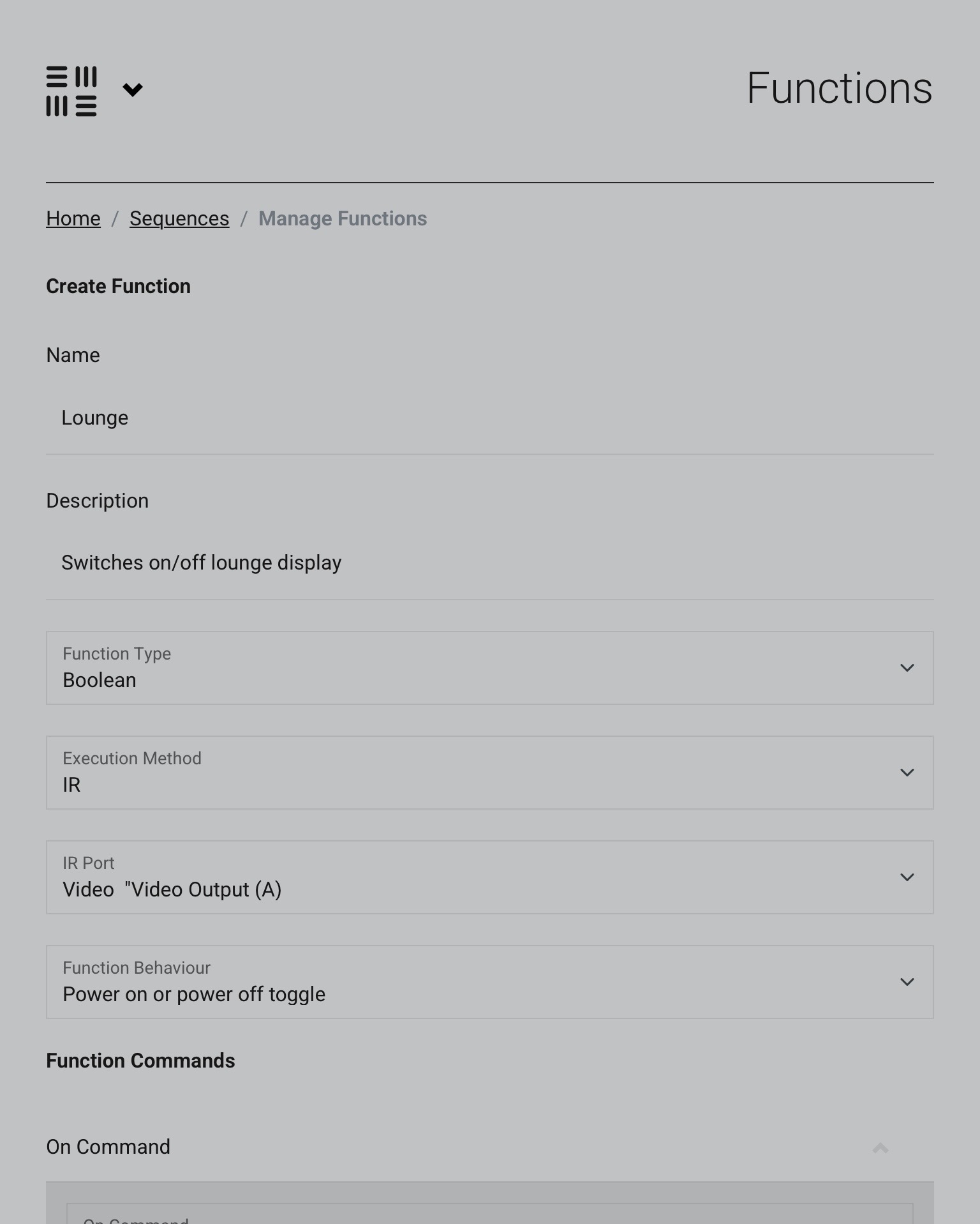
In this page label what your Function does, choose Boolean and whatever method you have been controlling this device by (in this case IR), and then the port at which the device is plugged into along with the command you wish to execute.
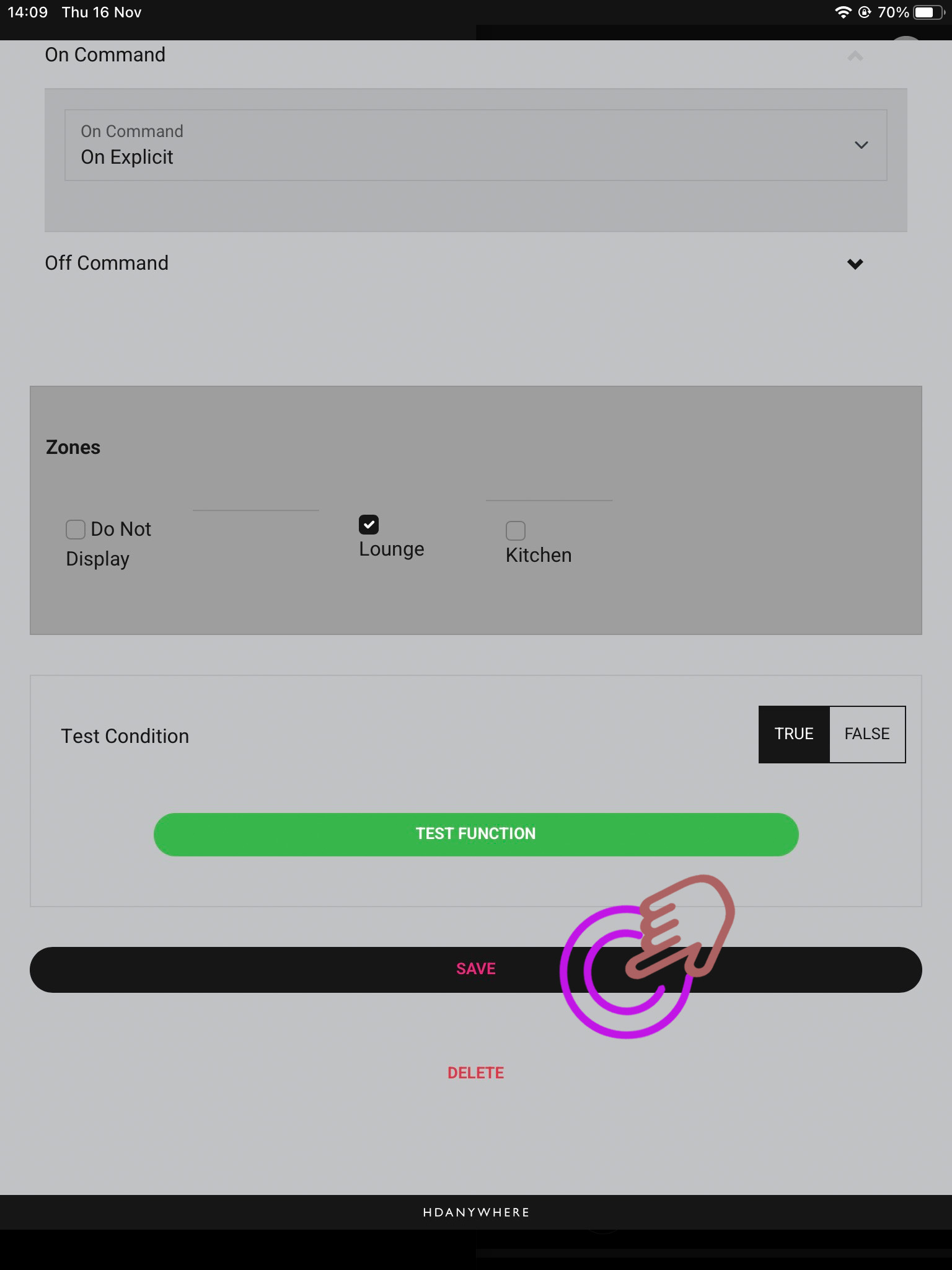
8. Zone selection
Certain zones won’t require your Functions to be present in them as the devices you’re controlling are in another room, so select which Functions are required where appropriate.
Open uControl
Settings
Access system
Sequences
webUI
Add new
Functions
Zones
As the method is Boolean, there will always be an on and an off command which can be toggled by pressing the Function in the app.
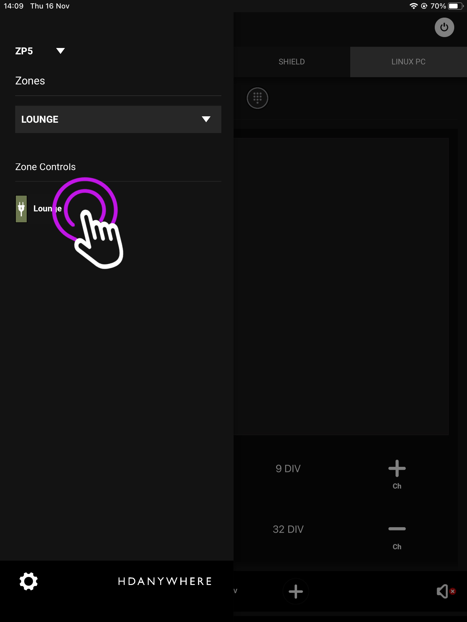
9. Activating your Function
Open the menu in the top left and you will see your available Sequences.
Open uControl
Settings
Access system
Sequences
webUI
Add new
Functions
Zones
Activating Function
You may have only selected a certain zone for your Sequence to be available in, to chnage between zones press the downward arrow and you can switch between them.
If your HDA device has uControl, you are able to setup Sequences which allow you to combine commands together to trigger a response from the system. This can be useful for scheduling certain actions like switching on/off a rooms devces at the push of a button.
From the main screen navigate to the menu in the top left.
Open uControl
What you see on the main screen may differ, however, the three lined menu bar will still be there.
2. Navigate to your settings
Look for the settings icon located in the bottom left corner.
Open uControl
Settings
The icon may vary depending on your mobile devices size, although it will still be in the bottom left corner.
3. Access System
From here press “Access System”.
Open uControl
Settings
Access System
This is your device page which displays your units model and IP address.
4. Sequences
In this menu press “Manage Sequences”.
Open uControl
Settings
Access System
Sequences
From this page you can also manage uControl IR/IP packs.
5. webUI
The webUI can also be easily accessed by typing you devices IP address into a website URL.
Open uControl
Settings
Access System
Sequences
webUI
You will be taken to the uOS home page, open the menu in the top left and select “Sequences”.
6. Add new Sequence
We are now in the sequences page where you can see your available sequences, and current functions. Press “Add New”.
Open uControl
Settings
Access System
Sequences
webUI
Add Sequence
A pop-up will appear asking if you’re creating a Function or Sequence, choose Sequence.
7. Input details
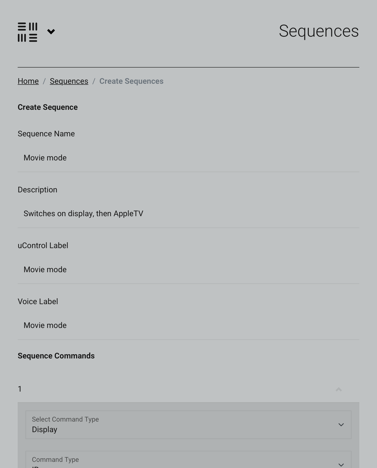
Now we need to input the details of your Sequence.
Open uControl
Settings
Access System
Sequences
webUI
Add Sequence
Make sure to label it so its clear what your sequence performs when you execute it.
8a. Adding your command(s)
We have the description of our Sequence, but now need to add the commands.
IP address
webUI
Add new Sequence
Input details
Adding your command(s)
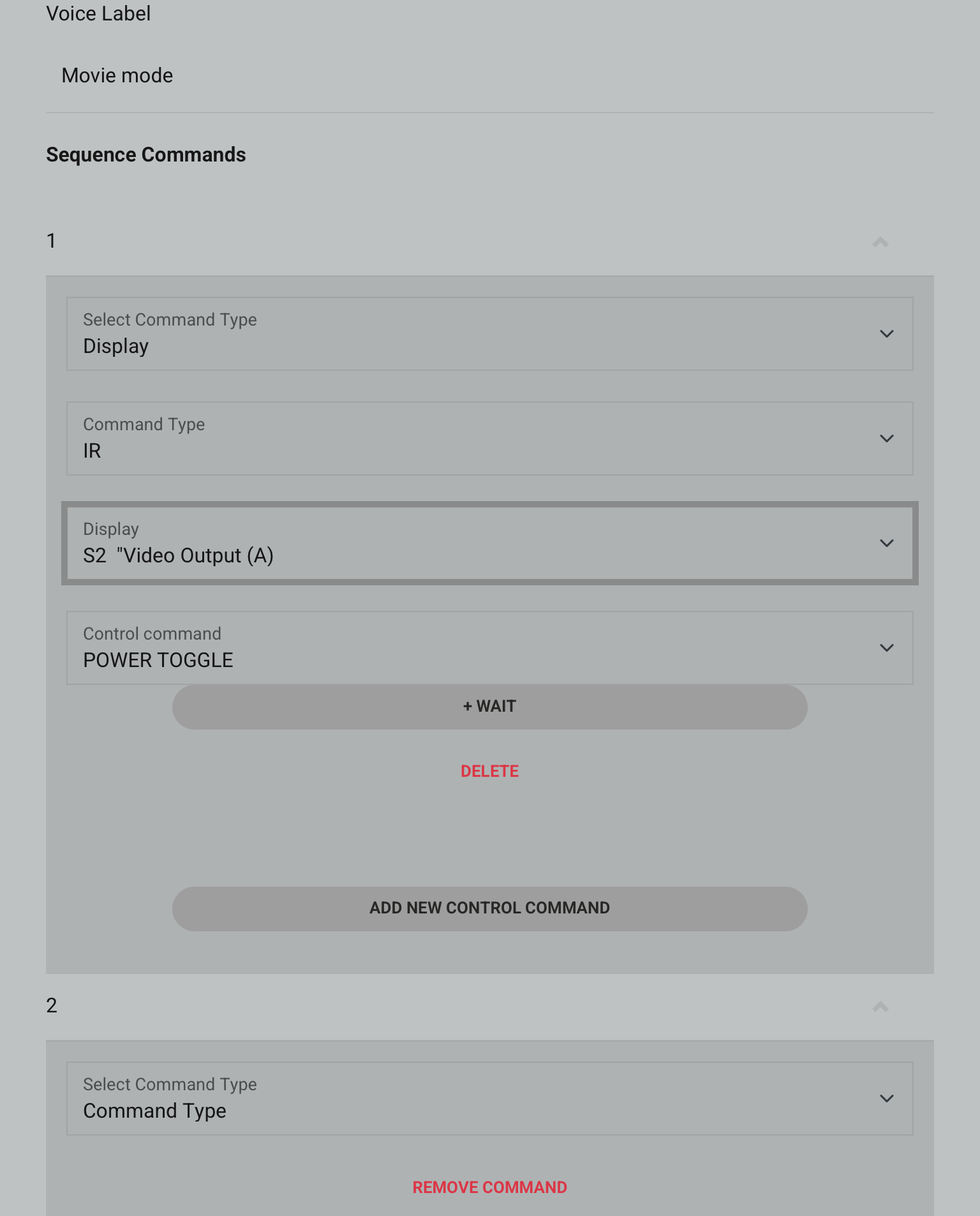
This first command is to switch the TV on or off, depending on the condition you set (True/False).
8b. Adding your command(s)
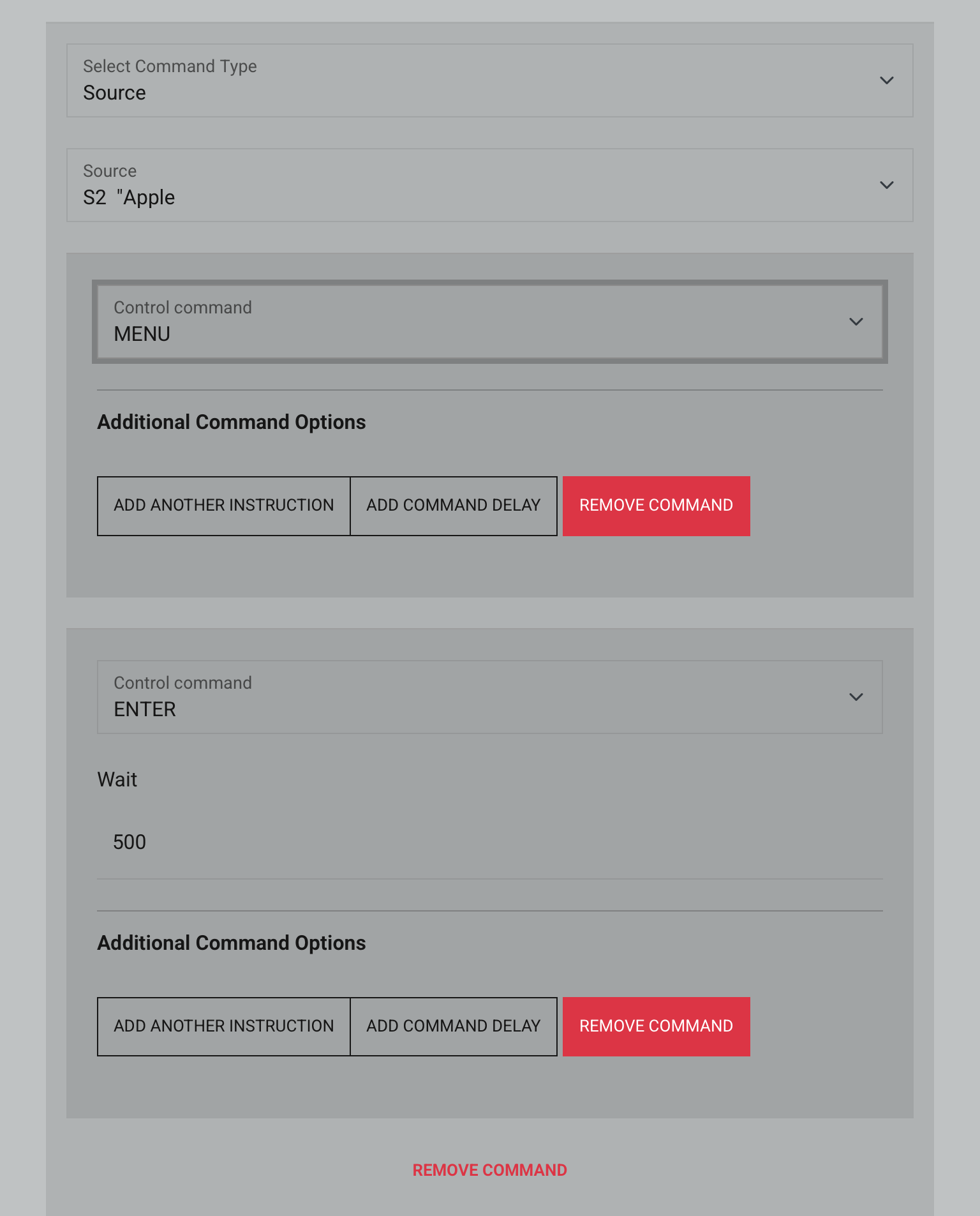
The next command speaks to the source device AppleTV by firstly going to the main menu. From here the next action command is “Enter”, which will open up AppleTV movies as it is the first icon in the menu. It also has a half a second delay before the second action is executed.
IP address
webUI
Add new Sequence
Input details
Adding your command(s)
There are plenty of commands to choose from and you can get quite creative.
9. Zone selection
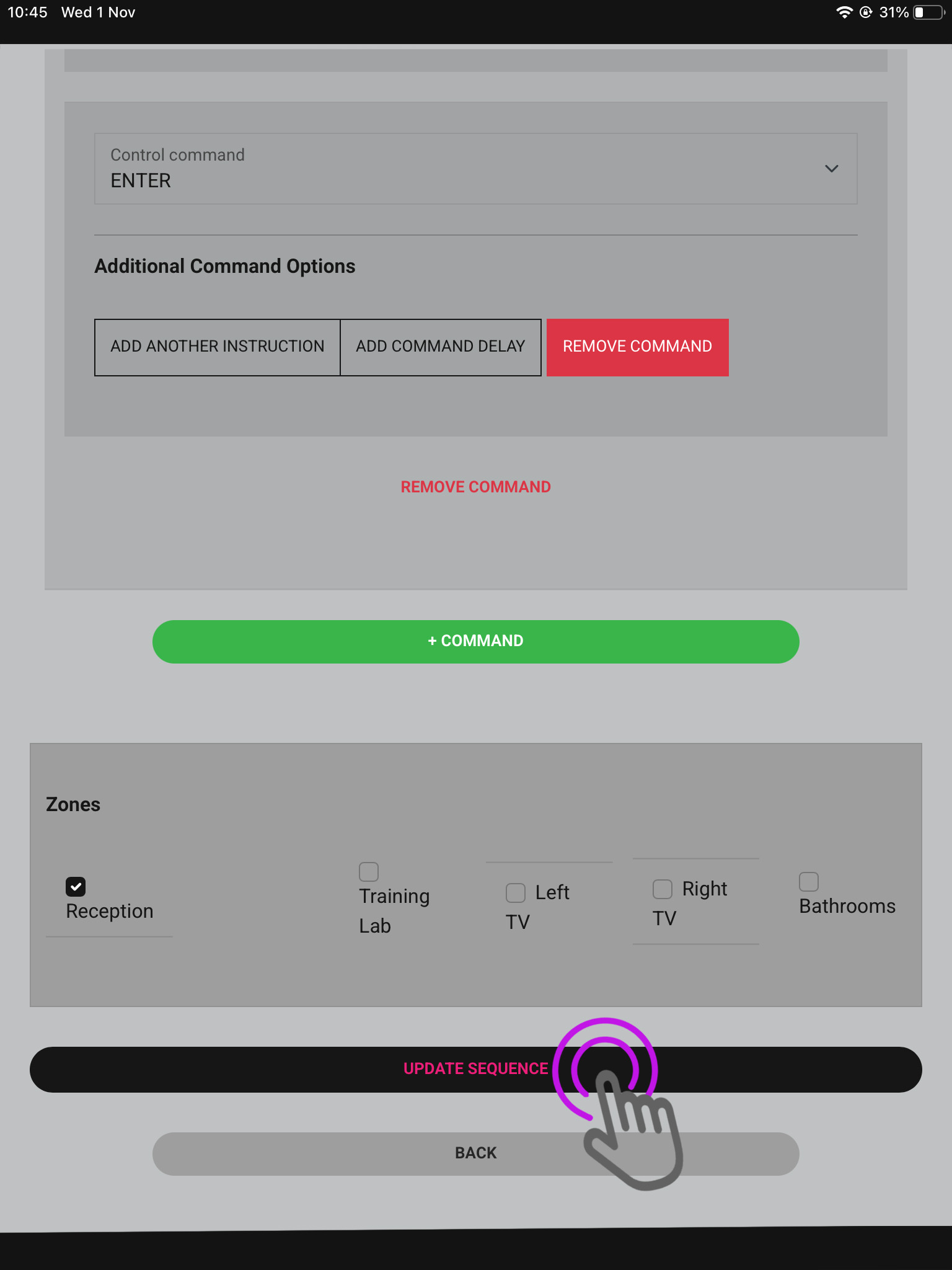
Certain rooms won’t require sequences to be present in them as the devices you’re controlling are in another room, so select which Sequences are required where appropriate.
IP address
webUI
Add new Sequence
Input details
Adding your command(s)
Zones
There are plenty of commands to choose from and you can get quite creative. Once finished press Update Sequence.
10. Activating your sequence
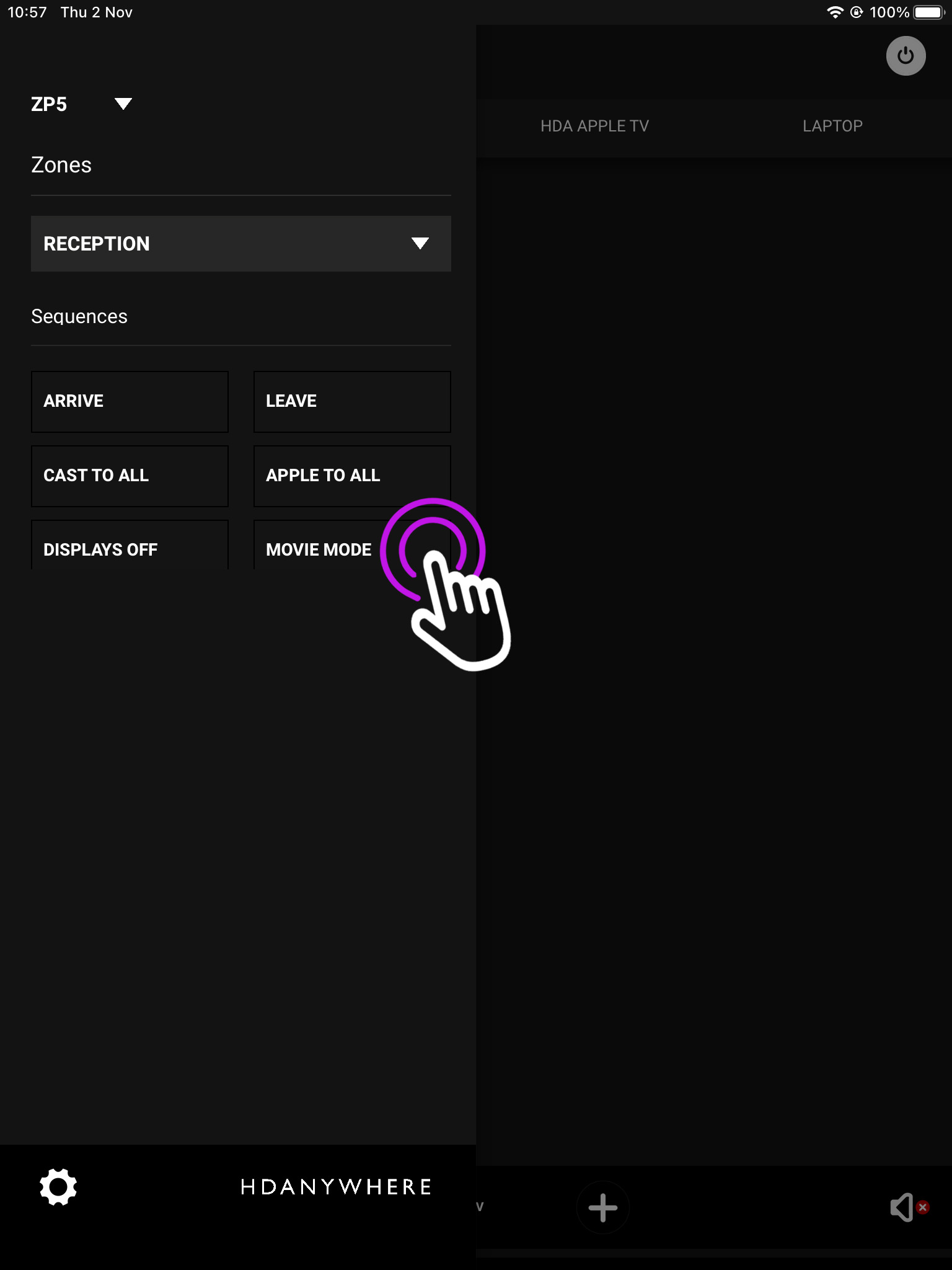
Open the menu in the top left and you will see your available Sequences.
IP address
webUI
Add new Sequence
Input details
Adding your command(s)
Zones
Activating Sequence
You may have only selected a certain zone for your Sequence to be available in, to chnage between zones press the downward arrow and you can switch between them.
Using a Rithum Switch along with an MHUB or Zone Prossesor you can use the device and uControl to execute sequences in uControl/uOS to control your home automation.
Using an Elgato Stream Deck along with an MHUB or Zone Prossesor you can use the Elgato device and our API to send commands to uControl/uOS to control virtually any display, source inputs and lighting control.