Tag: Modular 4×4

  • Software configuration tool for MHUB 2K and MHUB 4K (2014-2016)

    Windows configuration tool for MHUB 2K and MHUB 4K systems. Search for MHUB, configure EDID and network settings.

    Download the MHUB 2K and MHUB 4K configuration tool.

    The software configuration tool has been written for an older version of Windows. If you run the exe file on your laptop and you receive a C++ error message then please read this support article.

  • EDID management: Modular 4×4 and 8×8

    EDID (Extended Display Identification Data) is information provided by a display to describe its capabilities to a source. It contains information including resolution, audio formats and frame rates. Modular has the ability to ‘Fix’ the EDID profile to allow a source to always pass video with a fixed resolution and/or specific audio output (i.e 1080p 60Hz, with 5.1 multi-channel audio)

    If the system is functioning as normal, then no EDID management is required, however if you have a source that will not output the correct resolution/audio type, this can be resolved by following the instructions below

    Please remove the SD card from the unit and connect it to a PC (Please do not use a MAC). On the route of the SD card is a file called ‘settings.ini’, this is the file that will be edited. Open the file in a text editor such as notepad, then scroll down to the bottom of the file

    Enter one or more the following lines where required

    edidprofile1 = x     ; sets the EDID profile for source connected to input 1
    edidprofile2 = x     ; sets the EDID profile for source connected to input 2
    edidprofile3 = x     ; sets the EDID profile for source connected to input3
    edidprofile4 = x     ; sets the EDID profile for source connected to input4
    edidprofile5 = x     ; sets the EDID profile for source connected to input 5  (8×8 only)
    edidprofile6 = x     ; sets the EDID profile for source connected to input6 (8×8 only)
    edidprofile7 = x     ; sets the EDID profile for source connected to input 7 (8×8 only)
    edidprofile8 = x     ; sets the EDID profile for source connected to input 8 (8×8 only)

    where x equals:
    0 – Presents the source with the 1080p template EDID
    1 – Fixes the EDID
    2 – presents the source with the 4K template EDID
    3 – presents the source with the 1080p template EDID with 5.1 enabled
    101  – presents source with the EDID of the Sink connected to Output 1
    ..

    108  – presents the source with the EDID of the Sink connected to Output 8


    Once all editing has been done, save the settings.ini file, and reinsert the SD card back into the Modular unit.

    Also please reboot any source where the EDID profile has been modified to allow the new EDID data to be passed.

  • Modular and IR Control

    Modular units have the ability to receive Infra-red(IR) commands in two different ways; Code-based IR and Contextual based IR. Code-based IR uses unique codes for each room/output, whilst Contextual IR uses a single set of codes, with the unit determining where the IR command originated.

    If you wish to revert the unit to Code based IR control please edit the settings.ini file on the SD card (Please use only PC based systems to edit the SD card contents) and remove the following information.

    cir1 = 0x00ff9867
    cir2 = 0x00ffd827
    cir3 = 0x00ff8877
    cir4 = 0x00ffa857

    cir1 = 0x00ff807f
    cir2 = 0x00ff00ff
    cir3 = 0x00ff30cf
    cir4 = 0x00ff906f


  • Control Drivers for Modular Series (IP / RS232 / IR) – Modular 4×4, Modular 8×8 and mHub 4K (IP)

    Control Drivers for Modular Series (IP / RS232 / IR) – MOD44 and MOD88 & mHub 4K

    We have ready-made control system drivers available for Modular series systems for the major control systems used in the UK. These are currently IP based.

    (more…)

  • Modular IR, IP and Serial Commands (4×4 and 8×8)

    MOD44 / MOD88 control commands

    This video distribution range was discontinued in 2015 and only limited support will be provided from HDANYWHERE.

    A link to our control API can be found here for IR, IP and Serial commands.

  • HDanywhere Modular 8×8, 4×4 and mHub 4K Product Support For Loxone

    HDanywhere Modular 8×8, 4×4 and mHub 4K Product Support For Loxone

    We are pleased to say that we have an IP based ready-made control system driver for Loxone for HDanywhere Modular 8×8 and 4×4 and the mHub 4K. The driver currently supports video switching and may grow to encompass larger parts of the API over time. The driver now comes bundled inside the Loxone Config software so no download is required.

    (more…)

  • Modular 8×8, 4×4 & mHub 4K IP, RS232 and IR Control Information

    The Modular range of products and the mHub 4k support control via I.P., Rs232 and Infrared.

    All the settings and control strings for each of these control methods are located here – Modular Control

  • Using a multi-channel 5.1 / 7.1 amplifier receiver AVR with a matrix

    Using multichannel 5.1 / 7.1 amps AVR with matrix systems

    Essential Knowledge
    To understand how multichannel (5.1 / 7.1 etc) audio/sound is routed via a HDMI or HDBaseT matrix system, it is important to firstly acknowledge that all HDMI source devices (Blu-ray players, set-top-boxes, media servers, PCs etc) can only output a single audio format type at any one time. This is a limitation of HDMI itself.

    For example, the HDMI port on a Blu-Ray player cannot simultaneously output HDMI with 2.0ch stereo as well as HDMI with 7.1 DTS Master audio. It is always one or the other.

    arctical

    With only displays connected to the matrix
    When a matrix has only displays connected, with no AMPS/AVR in your set up, routing audio is relatively easy. This is because displays generally only have two speakers, and so a single HDMI format of HDMI+2.0ch can be routed to all displays. This gives you video and audio at every display.

    Adding an AVR/AMP the matrix
    When adding an AMP/AVR to the connected device mix, you are adding a component that can accept a multichannel audio format, such as 5.1 or 7.1.

    You now have a situation whereby some connected devices (displays) can only accept HDMI with 2.0ch stereo and some (the AVR/Amp) can accept HDMI with multichannel audio.

    What to expect in a mixed display / AVR setup
    Video matrixes operate on a “lowest common denominator” rule. This means that the matrix will exchange information with your displays and AVRs to decide on the format of audio to get from the source device; choosing the format that will ensure audio is output in all of your locations.

    One of two things can happen: If the AVR is turned on first and the matrix set to send a source capable of multi-channel audio to the AVR, the source will deliver multi-channel audio to the AVR. If a stereo TV is then turned on and the matrix then set to send the same source going to the AVR to the TV, the TV will be unable to play back the multi-channel audio. The result would be no sound from the TV.

    In the reverse, if a TV is turned on first and the matrix is set to send one of the connected sources, the source will deliver stereo audio to the TV via the matrix. If the AVR is then switched on and the matrix set to deliver the same source going to the TV, the AVR will only receive stereo audio.

    It is important to re-iterate, this is not a product limitation of HDanywhere matrixes. This is a limitation of HDMI technology itself and its specification.

    A solution is therefore required whereby the source device always sends multichannel audio to the AMP/AVR and 2.0ch stereo audio to the displays.

    Solution options
    There are many ways to solve this problem. Some complicated, some easier. Things will depend on the location of your equipment and the number of AVRs. We are always happy to help you build a specific solution that meets your setup. Here we can only cover some of the more common setup examples and a single solution to those.

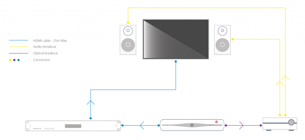
    I have a single AVR located beside / local to my source devices and the matrix e.g. in a cupboard / AV rack.
    In this type of setup, where the AVR for the multi-channel room is located with the sources and matrix itself, one solution is to deliver the audio to your AVR via alternative connectors to the HDMI where possible. For example, Sky HD boxes and Blu-Ray players usually have a digital audio output that can be connected to the AVR** via optical cabling. This can deliver multi-channel audio to the AVR over the optical cable, whilst the HDMI output from the source device can deliver 2.0 ch stereo audio to your matrix and therefore your other TV (stereo) locations in your setup. If this setup is located away from the room with multi-channel speakers fitted, say an under-stairs cupboard, there are solutions to keep IR control of your AVR that we can help with.

    arctical

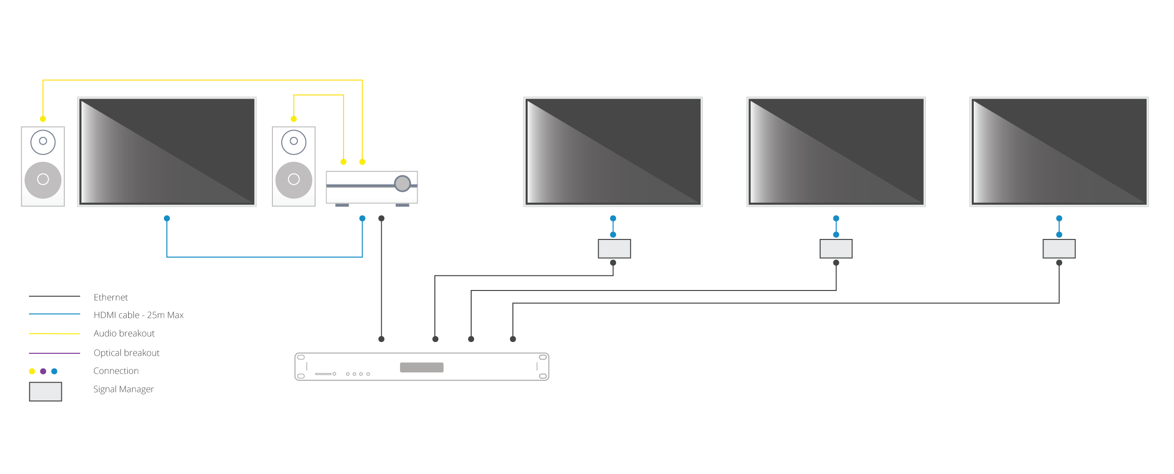
    AVRs located in the room with the displays
    In this type of setup, where AVR(s) are located in the rooms local to the displays, make sure the HDMI device is set to output 5.1 / 7.1 channel audio. This audio format will be sent over the Cat cable to each display location. In order to get audio out of your HDTVs (in say three rooms) and the AVR (connected to HDTV in a fourth room), some additional hardware is needed. HDanywhere sell a signal manager. Place 1 x signal manager at each TV that needs 2.0 channel audio aka. each TV that does not have an AVR.  Use a HDMI cable to connect the HDMI output port of the matrix’s display receiver to the HDMI input port of the Signal manager. Then use another HDMI cable to connect the HDMI output port of the Signal Manager to the HDMI port on the HDTV. So, the Signal Manager sits in between the display receiver and the HDTV.

    arctical2

    The Signal Manager has a box labelled “Audio”. The little switch on this audio section needs toggled to number 2: LPCM 2.0 before you connect up and turn on all your HDMI source devices and displays. Do not switch toggle the switch from no. 1 to no. 2 whilst displays and HDMI sourced devices are on. If you do so, you will need to power down the re-power all source devices and displays.

    Once the signal manager is set up and in place it will take 5.1 and output it as 2.0, ready to be accepted and then output by the HDTV. This should hopefully resolve your issue and deliver 5.1 to your AVR and 2.0 to your HDTV.

    Buy HDanywhere Signal Manager 

    Notes:
    *Multichannel audio via HDMI includes the following formats: LPCMDolby DigitalDTSDVD-AudioSuper Audio CDDolby Digital PlusDolby TrueHD,DTS-HD High Resolution AudioDTS-HD Master Audio, MPCM, DSDDST

    **When using alternative audio connectors other than HDMI, support for DTS-HD Master Audio and Dolby True HD is lost.

  • HDBaseT Product Distance Capability Notes

    HDBaseT Product Distance Capability Notes

    Products based on HDBaseT are based on one of two groups of electronic chips. The HDBaseT-Pro and HDBaseT-Lite groups. Each has different distances over which it can extend HDMI and this also depends on the type of cable used.

    (more…)

  • What do the flashing lights on my HDBaseT receivers mean?


    1. HDCP indictor light – shows whether a handshake between that display and source has been authenticated

    2. Link indicator light – confirms the TV receiver is connected to the hub

    3. Mode indicator light – if flashing all is correct

    4. Power indicator light – Lit when the TV receiver is on